Solids-involved equipment: Difference between revisions
(Undo revision 5220 by Johnmarsiglio (talk)) |
|||
| (47 intermediate revisions by the same user not shown) | |||
| Line 6: | Line 6: | ||
== Introduction and Overview == |
== Introduction and Overview == |
||
Solids- |
Solids-involved equipment are important pieces of many processes. Solids are often more difficult to handle than liquids because the process equipment consumes more energy to operate, are more prone to mechanical failure, and can create dust. Dusts can be very dangerous. They can cause respiratory illnesses and, in cases of combustible dust such as the Domino sugar plant, cause explosions in confined spaces. Flow of solids is also difficult to predict. While rheology is a well studied field for fluids, powder rheology is not a well characterized field. There are many pieces of process equipment aimed at handling solids. A bin is a vertical vessel used for storing solids. Large bins with with roughly a height to diameter ratio of 1.5 are called silos. Bins with height to diameter ratio less than this are called bunkers. From a silo or bunker solids will move out of an orifice, or hopper, to a feeder. Solids may be conveyed in a number of ways. The most familiar of these ways is a belt conveyer, like the ones used at the Domino sugar plant. There are also screw conveyors, which are used to convey free-flowing solids over short distances. Screw conveyors have been used since the time of Archimedes who made them famous with his Archimedes screw. Other types include hydraulic and pneumatic conveyors. |
||
bins with with roughly a height to diameter ratio of 1.5 are called silos. Bins with height to diameter ratio less than this are called bunkers. From a silo or bunker solids will move out of an orrifcae, or hopper, to a feeder. Solids may be conveyed in a number of ways. The most familiar of these ways is a belt conveyer, like the ones used at the Domino sugar plant. There are also screw conveyors, which are used to convey free-flowing solids over short distances. Screw conveyors have been used since the time of archemides who made them famous with his archemedies screw. Other types include hydraulic and pneumatic conveyors. |
|||
== Industrial Separation of Solids == |
== Industrial Separation of Solids == |
||
Currently there are many different ways to separate solids from liquids or gases. The most industrially important pieces of equipment are used to separate solid particles from gasses. A sector of this field, known as air pollution control is often glossed over in most chemical engineering undergraduate courses. However, it is an extremely important topic in industrial chemical plant design for reasons of employee health and EPA |
Currently there are many different ways to separate solids from liquids or gases. The most industrially important pieces of equipment are used to separate solid particles from gasses. A sector of this field, known as air pollution control is often glossed over in most chemical engineering undergraduate courses. However, it is an extremely important topic in industrial chemical plant design for reasons of employee health and EPA guidelines. However, there are other reasons to separate solids from gases, such as to prevent buildup of combustible dusts, as in the instance of the Domino sugar factory explosion, or to recover an expensive catalyst from a fluidized bed reactor. |
||
===Gravity Settlers=== |
===Gravity Settlers=== |
||
As the name implies, gravity settlers are simply a long chamber through which gas-solid systems are sent. Large particle sizes (>50um) can be removed from the system this way. |
As the name implies, gravity settlers are simply a long chamber through which gas-solid systems are sent. Over the length of the chamber larger particle settle out of the gas stream. Large particle sizes (>50um) can be removed from the system this way. The effectiveness of the settling chambers can be increased by disrupting gas flow with such features as baffles. Impingement separators use many baffles in this way to collect solid particles. The addition of baffles causes higher pressure drops than in simple settling chambers, but also allow for particle sizes down to 10um to be collected. The advantages of using gravity settlers for particle separations would be the low cost and their applications in high temperature, high pressure, or corrosive environments. |
||
===Cyclones=== |
===Cyclones=== |
||
When a gravity settler is insufficient, centrifugal separation can be employed. This piece of process equipment is known as a cyclone. A cyclone resembles an inverted cone, in which solid-gas systems enter along the side, |
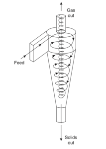
When a gravity settler is insufficient, centrifugal separation can be employed. This piece of process equipment is known as a cyclone. Like gravity settlers, cyclones can be used in high temperature, high pressure applications. A cyclone resembles an inverted cone, in which solid-gas systems enter along the side. As the gas stream swirls down towards the apex of the cyclone, particles contact the walls. This causes them to fall to the bottom. The cleaned gas stream will then exit at the top by moving upwards in a tighter spiral. Solids are removed from the cyclone via a hopper. See figure 1 for more details. Cyclones are particularly effective, able to handle particle sizes down to 5um. Along with having no moving parts, this makes them an industry favorite.[[File:cyclone.png|thumb|center|'''Figure 1''' Standard Reverse-flow Cyclone|500x300px]] |
||
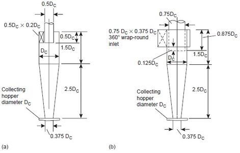
When designing a cyclone there are two main designs: high efficiency and high throughput. Cyclone choice should be based on the industrial application, and its requirements of gas cleaning. Figure 2 below compares the dimensional differences between (a) high efficiency cyclones and (b) high throughput cyclones. |
|||
[[File:Cyclone comparison.jpg|thumb|center|'''Figure 2''' High Efficiency and High Throughput Cyclones|500x300px]] |
|||
One method to help process engineers select the proper cyclone type is to use performance curves under standard conditions to compare high efficiency vs high throughput cyclones for their application. Another method is to use more than one cyclone in series to assist in solids handling. |
|||
===Baghouses=== |
|||
The particle control measure that the average consumer would be most familiar with would be the baghouse. A baghouse is a simple concept of many filters, and dust collection in bags, much like the home vacuum cleaner. These bags do not look much like the home vacuum cleaner bag. These bags are cylindrical made of a woven filter media. These media generally can handle modest industrial temperatures (~250 ºF). Baghouses work as process gas is drawn through the bags. Over time a thick layer of dust accumulates on the filters until. When the pressure drop over the bags gets too high cleaning must take place. Cleaning can be done manually or by a backpulse in the opposite direction of flow, after which the filter cake may be collected via a hopper. There are several mechanisms by which dust is collected. These include inertial collection, dust striking fibers perpendicular to changing gas stream, brownian motion collection, diffusion of very small particles into the fiber matrix, or electrostatic collection, a charged surface on the filter cake that attracts particles. Baghouses are very effective, and can handle particulates down to 10um. |
|||
===Scrubbers=== |
|||
Wet scrubbing is a very effective method for reducing dust in gas streams. A typical wet scrubbing system features a solid-gas stream flowing concurrently to a liquid (generally water,) stream. When particles impact the water stream they become trapped. Wet scrubbers can remove particle sizes down to 0.5um. While effective scrubbers are also expensive, which is why other less expensive means of air pollution control are often employed. |
|||
There are some typical applications for scrubbers to remove solids from gas streams. A common way to reduce an acid gas in an air stream involves the addition of an alkaline material (such as hydrated lime). This is called dry sorbent injection. The hydrated lime will react with the acid gas to form solid salts. Then the salts can be removed via a countercurrent scrubber. This is similar to a spray dryer absorber, where flue gas would be mixed with an atomized alkaline slurry before going to the scrubber. |
|||
===Electrostatic Precipitators=== |
|||
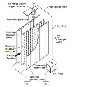
Electrostatic Precipitators, or ESPs, are some of the most effective air pollution control equipment. They can remove very fine particles down to around 0.5um. To do so the gas stream flows horizontally thorough spaces between rows of vertical wires followed by a stack of large, vertical, flat metal plates. A very large negative voltage is applied to the wires, which is capable of ionizing the gas around it. From there the negatively charged particles then collect on the positively charged precipitator plates to form a layer. This dust layer can provide additional resistivity, which is one factor that has a big impact on ESP performance. While incredibly effective, constructing and operating an ESP is very expensive, which is why they are only used when necessary in industry. |
|||
[[File:ESP.JPG|thumb|center|'''Figure 3''' Electrostatic Precipitator Layout|500x300px]] |
|||
== Solid Catalyst Involved Equipment == |
|||
An important part of solids involved equipment are also catalyst involved reactors. A catalyst increases the rate of a reaction without being involved in the products or reactants. Catalysts are also important from a selectivity standpoint. Under the proper conditions some catalysts allow for preferential selection of one reaction over many others. Despite the added cost of a catalyst, and the eventual cost of regenerating or replacing a catalyst, catalytic reactions are generally the cost effective route to making a product. While there are many types of catalysts this section will focus on solid catalysts processes and the equipment that facilitates their use. |
|||
===Fixed Bed Reactor=== |
|||
A fixed bed reactor features a stationary packed bed of catalyst through which a gas stream flows. These are the most common type of reactors to react high temperature gas streams. Fixed bed reactors range in size on the order of a few centimeters to a few meters in diameter. Like all vessels, the general limit on fixed bed reactor size is around 4 meters since sizes greater would require on site fabrication. |
|||
In a fixed bed reactor the gaseous reactant enters at the top of the reactor and flows through the catalyst bed. However, in some cases a radial flow is used. This is for very low pressure drops. This reactor would be an annulus with the annular space between the tubes packed with catalyst. Heat transfer is also an important feature in fixed bed reactors because they are often operated at temperatures well above ambient. An example process that uses a fixed bed reactor would be the Haber Process to fix nitrogen. |
|||
Towler and Sinnott outline a simple method for sizing a packed bed reactor needing only a space velocity. This method is outlined here [https://processdesign.mccormick.northwestern.edu/index.php/Reactors#Heterogeneous_Catalysis] |
|||
===Moving bed Reactors=== |
|||
Moving bed reactors are a noteworthy special case of fixed bed reactors. In any catalytic reaction the catalyst will lose effectiveness over time. Generally at some point in the life of a fixed bed reactor the catalyst needs either to be regenerated or replaced. A moving bed reactor addresses this issue by allowing for gradual solids change out. This allows for more efficient bed operation. An example process that uses a moving bed reactor would be the catalytic reforming of naphtha. |
|||
===Fluidized Bed Reactors=== |
|||
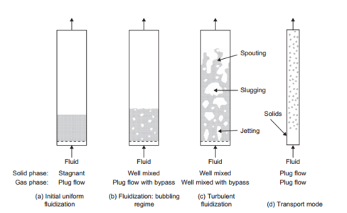
In the case of very rapid catalyst fouling, a fluidized bed is the reactor of choice. Fluidized beds work by fluidizing the solid catalyst particles with the gas stream. Different types of fluidization correspond to different flow regimes (see below). |
|||
[[File:Fluidized bed.PNG|thumb|center|'''Figure 4''' Fluidized Bed Flow Regimes|500x300px]] |
|||
Fluidized beds are commonly used in catalytic cracking processes of heavy oils. The limitations on the fluidized bed is that the particle size must be small (<300um), and be able to withstand the attrition of hitting other particles and the walls of the reactor. These reactors also require a special separation process in order to not carry away solids in the product stream. This is most commonly done with a few cyclones in series. |
|||
==HYSYS Simulation== |
|||
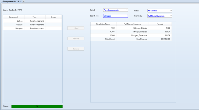
AspenTech HYSYS can be a powerful tool to simulate the use of solids involved equipment in handling solids. One widely used piece of solids involved equipment is the cyclone which, in its many forms, can be used to remove solids from a gas stream. This case study will focus on removing soot (carbon) from the flue gas of a coal burning power plant. Various carbon compounds are very common solid particles that cyclones are able to remove. To begin the appropriate gases (in this case nitrogen and oxygen,) must be added to the simulation along with the solid. HYSYS does not have many solids to choose from in the simulation. |
|||
[[File:Component list 1.PNG|thumb|center|'''Figure 5''' Component Selection|675x775px]] |
|||
The choice of fluid package depends greatly on the fluids and the operating conditions. In this case the general NRTL is sufficient. |
|||
[[File:2nd choose fluid package.PNG|thumb|center|'''Figure 6''' Fluid Package Selection|675x775px]] |
|||
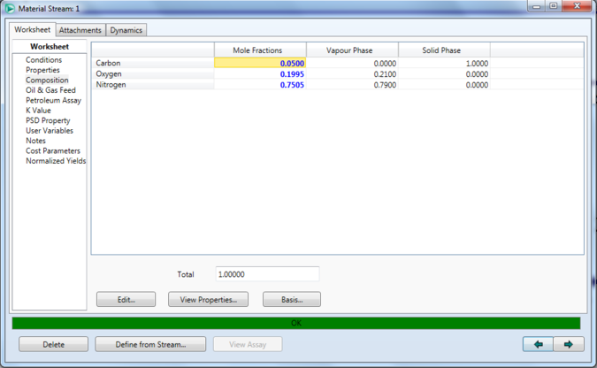
From here the simulation environment is ready. Start by specifying a feed stream. In this case a soot heavy feed is specified to be cleaned. [[File:Composition on material stream 1.PNG|thumb|center|'''Figure 7''' Feed Specification|675x775px]] |
|||
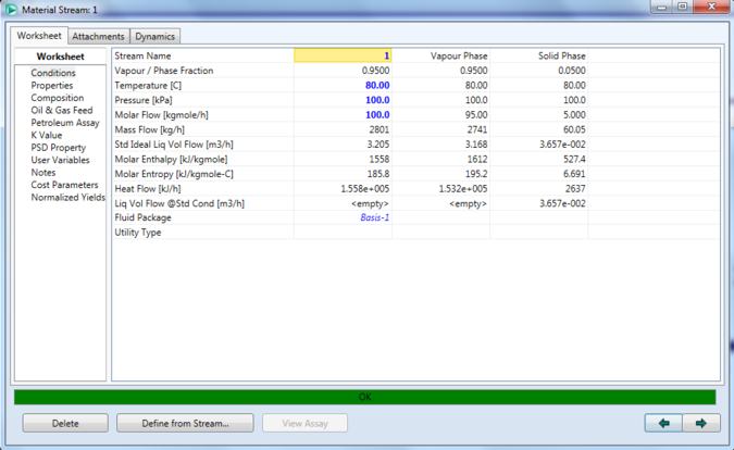
Next the flue gas conditions must be specified. Here the flue gas is at atmospheric pressure and elevated temperature. |
|||
[[File:Conditions on material stream 1.PNG|thumb|center|'''Figure 8''' Material Stream Conditions|675x775px]] |
|||
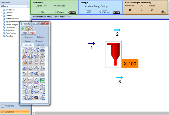
Next the cyclone can be placed in the environment, and the appropriate streams may be attached to the appropriate positions. The simulation should look something like below. |
|||
[[File:Addcyclone.PNG|thumb|center|'''Figure 9''' Simulation Environment|675x775px]] |
|||
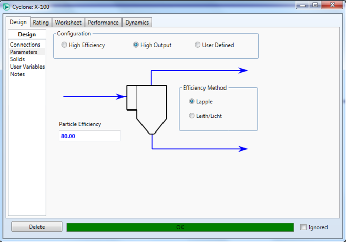
The cyclone needs a few specifications before the simulation will converge. Under parameters the efficiency method and particle efficiency must be specified. The Lapple method is the simpler of the two and generally good, although in some cases the Leith-Licht theory is a better approximation. Either is fine for this simulation. This is also the point where high throughput or high efficiency cyclone type must be specified. In this example the high-throughput will be used assuming this coal plant produces a lot of flue gas. Particle efficiencies for cyclones generally run on the order of 50-80%. |
|||
[[File:High output 1.PNG|thumb|center|'''Figure 10''' Parameter Specification|675x775px]] |
|||
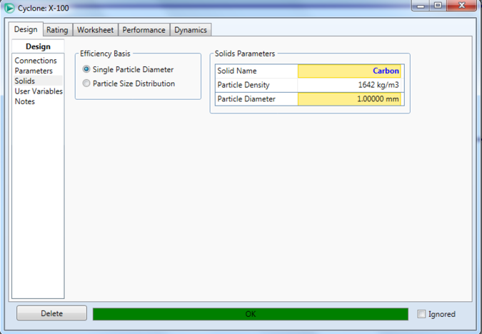
Now the solid component must be specified. For the cyclone to converge the particle size must also be specified. This may either be in the form of a single particle size, or a particle size distribution centered around a value. In this case a single particle size is selected, but in the case of selecting a particle size distribution the largest particle size must also be specified. |
|||
[[File:Particle diameter 1.PNG|thumb|center|'''Figure 11''' Solid and Particle Size Specification|675x775px]] |
|||
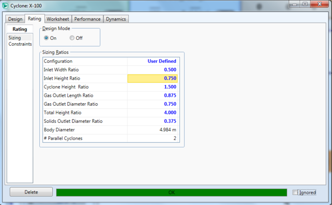
At this point the cyclone should be converged. The cyclone can also be sized in the convenient design mode feature under sizing. These parameters can also be user defined. For a detailed description of cyclone sizing please see Sinnott and Towler. |
|||
[[File:Sizing.PNG|thumb|center|'''Figure 12''' Sizing Specifications|675x775px]] |
|||
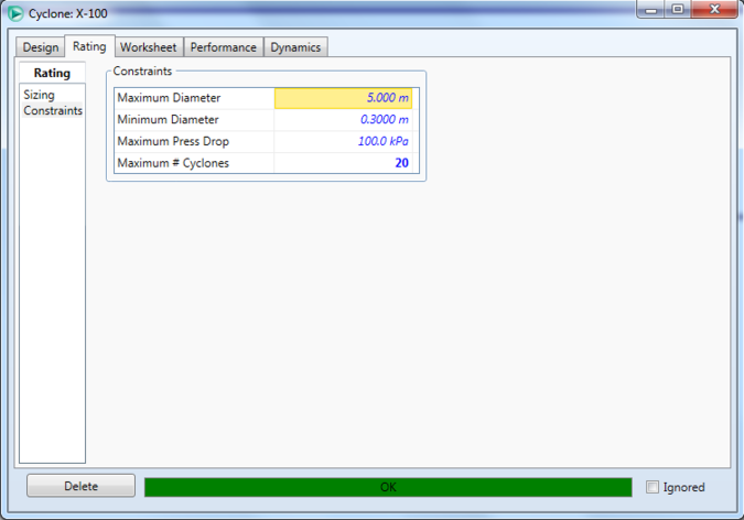
Finally if the system is not converging after specifying the particle size, the constraints on the cyclone will have to be modified under the constraints tab. Either the maximum number of cyclones or the maximum pressure drop needs to be increased to get a cyclone that is not converging to converge. |
|||
[[File:Constraints 1.PNG|thumb|center|'''Figure 13''' Constraints|675x775px]] |
|||
This constraints window also has the added feature of listing the number of cyclones in parallel that would be needed to handle the specified gas input stream. |
|||
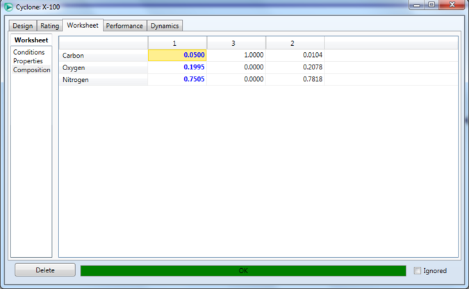
To view how effective this cyclone is, simply select composition under the worksheet tab. Here one cyclone achieves the 80% efficiency that was specified. |
|||
[[File:Composition results.PNG|thumb|center|'''Figure 14''' Soot Reduction Results|675x775px]] |
|||
Should environmental regulation require a lower emission level, another cyclone can be added in series. Here the same procedure is followed: |
|||
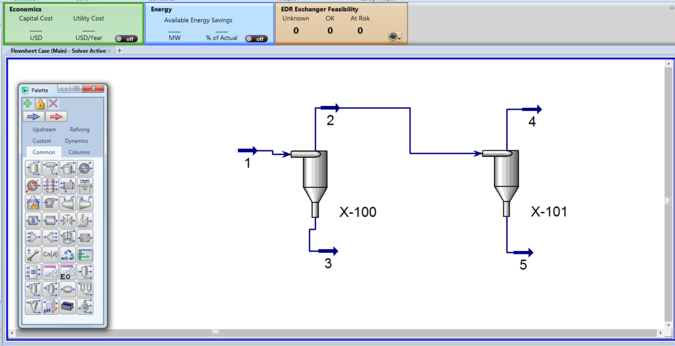
[[File:Second cyclone in series.PNG|thumb|center|'''Figure 15''' Second Cyclone in Series|675x775px]] |
|||
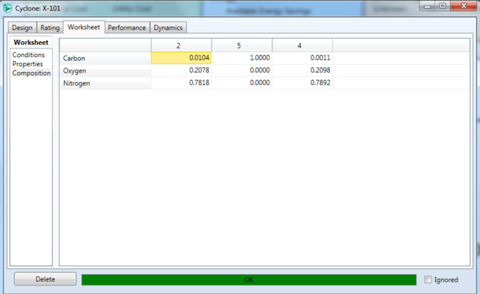
Checking again this second cyclone also achieves its target efficiency. |
|||
[[File:Second cyclone effectiveness.PNG|thumb|center|'''Figure 16''' Second Cyclone Soot Reduction Results|675x775px]] |
|||
==Conclusion== |
|||
Solids involved process equipment are an essential piece of the chemicals industry. Unfortunately most undergraduate process design courses spend little time covering their applications. However, the design of solids involved process equipment is straightforward, and with the appropriate references, and powerful simulation tools such as HYSYS, the design of solids involved process equipment should not be a daunting task for the entry level process engineer. |
|||
=== |
==References== |
||
# G.P. Towler, R. Sinnott, Chemical Engineering Design: Principles, Practice and Economics of Plant and Process Design, Elsevier, 2013. |
|||
# R.H. Perry, D. W. Green, Eds., Perry’s Chemical Engineers’ Handbook, 6th Ed., McGrawHill: New York, 1984. |
|||
# L.T. Biegler, I.E. Grossmann, A.W. Westerberg, Systematic Methods of Chemical Process Design, Prentice-Hall: Upper Saddle River, 1997. |
|||
# W.D. Seider, J.D. Seader, D.R. Lewin, Process Design Principles: Synthesis, Analysis, and Evaluation, Wiley: New York, 2004. |
|||
# R.T. Turton, R.C. Bailie, W.B. Whiting, J.A. Shaeiwitz, Analysis, Synthesis, and Design of Chemical Processes, Prentice Hall: Upper Saddle River, 2003. |
|||
Latest revision as of 20:58, 11 March 2016
Author: John Marsiglio [2016]
Stewards: Daniel Garcia and Fengqi You
Introduction and Overview
Solids-involved equipment are important pieces of many processes. Solids are often more difficult to handle than liquids because the process equipment consumes more energy to operate, are more prone to mechanical failure, and can create dust. Dusts can be very dangerous. They can cause respiratory illnesses and, in cases of combustible dust such as the Domino sugar plant, cause explosions in confined spaces. Flow of solids is also difficult to predict. While rheology is a well studied field for fluids, powder rheology is not a well characterized field. There are many pieces of process equipment aimed at handling solids. A bin is a vertical vessel used for storing solids. Large bins with with roughly a height to diameter ratio of 1.5 are called silos. Bins with height to diameter ratio less than this are called bunkers. From a silo or bunker solids will move out of an orifice, or hopper, to a feeder. Solids may be conveyed in a number of ways. The most familiar of these ways is a belt conveyer, like the ones used at the Domino sugar plant. There are also screw conveyors, which are used to convey free-flowing solids over short distances. Screw conveyors have been used since the time of Archimedes who made them famous with his Archimedes screw. Other types include hydraulic and pneumatic conveyors.
Industrial Separation of Solids
Currently there are many different ways to separate solids from liquids or gases. The most industrially important pieces of equipment are used to separate solid particles from gasses. A sector of this field, known as air pollution control is often glossed over in most chemical engineering undergraduate courses. However, it is an extremely important topic in industrial chemical plant design for reasons of employee health and EPA guidelines. However, there are other reasons to separate solids from gases, such as to prevent buildup of combustible dusts, as in the instance of the Domino sugar factory explosion, or to recover an expensive catalyst from a fluidized bed reactor.
Gravity Settlers
As the name implies, gravity settlers are simply a long chamber through which gas-solid systems are sent. Over the length of the chamber larger particle settle out of the gas stream. Large particle sizes (>50um) can be removed from the system this way. The effectiveness of the settling chambers can be increased by disrupting gas flow with such features as baffles. Impingement separators use many baffles in this way to collect solid particles. The addition of baffles causes higher pressure drops than in simple settling chambers, but also allow for particle sizes down to 10um to be collected. The advantages of using gravity settlers for particle separations would be the low cost and their applications in high temperature, high pressure, or corrosive environments.
Cyclones
When a gravity settler is insufficient, centrifugal separation can be employed. This piece of process equipment is known as a cyclone. Like gravity settlers, cyclones can be used in high temperature, high pressure applications. A cyclone resembles an inverted cone, in which solid-gas systems enter along the side. As the gas stream swirls down towards the apex of the cyclone, particles contact the walls. This causes them to fall to the bottom. The cleaned gas stream will then exit at the top by moving upwards in a tighter spiral. Solids are removed from the cyclone via a hopper. See figure 1 for more details. Cyclones are particularly effective, able to handle particle sizes down to 5um. Along with having no moving parts, this makes them an industry favorite.
When designing a cyclone there are two main designs: high efficiency and high throughput. Cyclone choice should be based on the industrial application, and its requirements of gas cleaning. Figure 2 below compares the dimensional differences between (a) high efficiency cyclones and (b) high throughput cyclones.
One method to help process engineers select the proper cyclone type is to use performance curves under standard conditions to compare high efficiency vs high throughput cyclones for their application. Another method is to use more than one cyclone in series to assist in solids handling.
Baghouses
The particle control measure that the average consumer would be most familiar with would be the baghouse. A baghouse is a simple concept of many filters, and dust collection in bags, much like the home vacuum cleaner. These bags do not look much like the home vacuum cleaner bag. These bags are cylindrical made of a woven filter media. These media generally can handle modest industrial temperatures (~250 ºF). Baghouses work as process gas is drawn through the bags. Over time a thick layer of dust accumulates on the filters until. When the pressure drop over the bags gets too high cleaning must take place. Cleaning can be done manually or by a backpulse in the opposite direction of flow, after which the filter cake may be collected via a hopper. There are several mechanisms by which dust is collected. These include inertial collection, dust striking fibers perpendicular to changing gas stream, brownian motion collection, diffusion of very small particles into the fiber matrix, or electrostatic collection, a charged surface on the filter cake that attracts particles. Baghouses are very effective, and can handle particulates down to 10um.
Scrubbers
Wet scrubbing is a very effective method for reducing dust in gas streams. A typical wet scrubbing system features a solid-gas stream flowing concurrently to a liquid (generally water,) stream. When particles impact the water stream they become trapped. Wet scrubbers can remove particle sizes down to 0.5um. While effective scrubbers are also expensive, which is why other less expensive means of air pollution control are often employed. There are some typical applications for scrubbers to remove solids from gas streams. A common way to reduce an acid gas in an air stream involves the addition of an alkaline material (such as hydrated lime). This is called dry sorbent injection. The hydrated lime will react with the acid gas to form solid salts. Then the salts can be removed via a countercurrent scrubber. This is similar to a spray dryer absorber, where flue gas would be mixed with an atomized alkaline slurry before going to the scrubber.
Electrostatic Precipitators
Electrostatic Precipitators, or ESPs, are some of the most effective air pollution control equipment. They can remove very fine particles down to around 0.5um. To do so the gas stream flows horizontally thorough spaces between rows of vertical wires followed by a stack of large, vertical, flat metal plates. A very large negative voltage is applied to the wires, which is capable of ionizing the gas around it. From there the negatively charged particles then collect on the positively charged precipitator plates to form a layer. This dust layer can provide additional resistivity, which is one factor that has a big impact on ESP performance. While incredibly effective, constructing and operating an ESP is very expensive, which is why they are only used when necessary in industry.
Solid Catalyst Involved Equipment
An important part of solids involved equipment are also catalyst involved reactors. A catalyst increases the rate of a reaction without being involved in the products or reactants. Catalysts are also important from a selectivity standpoint. Under the proper conditions some catalysts allow for preferential selection of one reaction over many others. Despite the added cost of a catalyst, and the eventual cost of regenerating or replacing a catalyst, catalytic reactions are generally the cost effective route to making a product. While there are many types of catalysts this section will focus on solid catalysts processes and the equipment that facilitates their use.
Fixed Bed Reactor
A fixed bed reactor features a stationary packed bed of catalyst through which a gas stream flows. These are the most common type of reactors to react high temperature gas streams. Fixed bed reactors range in size on the order of a few centimeters to a few meters in diameter. Like all vessels, the general limit on fixed bed reactor size is around 4 meters since sizes greater would require on site fabrication. In a fixed bed reactor the gaseous reactant enters at the top of the reactor and flows through the catalyst bed. However, in some cases a radial flow is used. This is for very low pressure drops. This reactor would be an annulus with the annular space between the tubes packed with catalyst. Heat transfer is also an important feature in fixed bed reactors because they are often operated at temperatures well above ambient. An example process that uses a fixed bed reactor would be the Haber Process to fix nitrogen.
Towler and Sinnott outline a simple method for sizing a packed bed reactor needing only a space velocity. This method is outlined here [1]
Moving bed Reactors
Moving bed reactors are a noteworthy special case of fixed bed reactors. In any catalytic reaction the catalyst will lose effectiveness over time. Generally at some point in the life of a fixed bed reactor the catalyst needs either to be regenerated or replaced. A moving bed reactor addresses this issue by allowing for gradual solids change out. This allows for more efficient bed operation. An example process that uses a moving bed reactor would be the catalytic reforming of naphtha.
Fluidized Bed Reactors
In the case of very rapid catalyst fouling, a fluidized bed is the reactor of choice. Fluidized beds work by fluidizing the solid catalyst particles with the gas stream. Different types of fluidization correspond to different flow regimes (see below).
Fluidized beds are commonly used in catalytic cracking processes of heavy oils. The limitations on the fluidized bed is that the particle size must be small (<300um), and be able to withstand the attrition of hitting other particles and the walls of the reactor. These reactors also require a special separation process in order to not carry away solids in the product stream. This is most commonly done with a few cyclones in series.
HYSYS Simulation
AspenTech HYSYS can be a powerful tool to simulate the use of solids involved equipment in handling solids. One widely used piece of solids involved equipment is the cyclone which, in its many forms, can be used to remove solids from a gas stream. This case study will focus on removing soot (carbon) from the flue gas of a coal burning power plant. Various carbon compounds are very common solid particles that cyclones are able to remove. To begin the appropriate gases (in this case nitrogen and oxygen,) must be added to the simulation along with the solid. HYSYS does not have many solids to choose from in the simulation.
The choice of fluid package depends greatly on the fluids and the operating conditions. In this case the general NRTL is sufficient.
From here the simulation environment is ready. Start by specifying a feed stream. In this case a soot heavy feed is specified to be cleaned.
Next the flue gas conditions must be specified. Here the flue gas is at atmospheric pressure and elevated temperature.
Next the cyclone can be placed in the environment, and the appropriate streams may be attached to the appropriate positions. The simulation should look something like below.
The cyclone needs a few specifications before the simulation will converge. Under parameters the efficiency method and particle efficiency must be specified. The Lapple method is the simpler of the two and generally good, although in some cases the Leith-Licht theory is a better approximation. Either is fine for this simulation. This is also the point where high throughput or high efficiency cyclone type must be specified. In this example the high-throughput will be used assuming this coal plant produces a lot of flue gas. Particle efficiencies for cyclones generally run on the order of 50-80%.
Now the solid component must be specified. For the cyclone to converge the particle size must also be specified. This may either be in the form of a single particle size, or a particle size distribution centered around a value. In this case a single particle size is selected, but in the case of selecting a particle size distribution the largest particle size must also be specified.
At this point the cyclone should be converged. The cyclone can also be sized in the convenient design mode feature under sizing. These parameters can also be user defined. For a detailed description of cyclone sizing please see Sinnott and Towler.
Finally if the system is not converging after specifying the particle size, the constraints on the cyclone will have to be modified under the constraints tab. Either the maximum number of cyclones or the maximum pressure drop needs to be increased to get a cyclone that is not converging to converge.
This constraints window also has the added feature of listing the number of cyclones in parallel that would be needed to handle the specified gas input stream.
To view how effective this cyclone is, simply select composition under the worksheet tab. Here one cyclone achieves the 80% efficiency that was specified.
Should environmental regulation require a lower emission level, another cyclone can be added in series. Here the same procedure is followed:
Checking again this second cyclone also achieves its target efficiency.
Conclusion
Solids involved process equipment are an essential piece of the chemicals industry. Unfortunately most undergraduate process design courses spend little time covering their applications. However, the design of solids involved process equipment is straightforward, and with the appropriate references, and powerful simulation tools such as HYSYS, the design of solids involved process equipment should not be a daunting task for the entry level process engineer.
References
- G.P. Towler, R. Sinnott, Chemical Engineering Design: Principles, Practice and Economics of Plant and Process Design, Elsevier, 2013.
- R.H. Perry, D. W. Green, Eds., Perry’s Chemical Engineers’ Handbook, 6th Ed., McGrawHill: New York, 1984.
- L.T. Biegler, I.E. Grossmann, A.W. Westerberg, Systematic Methods of Chemical Process Design, Prentice-Hall: Upper Saddle River, 1997.
- W.D. Seider, J.D. Seader, D.R. Lewin, Process Design Principles: Synthesis, Analysis, and Evaluation, Wiley: New York, 2004.
- R.T. Turton, R.C. Bailie, W.B. Whiting, J.A. Shaeiwitz, Analysis, Synthesis, and Design of Chemical Processes, Prentice Hall: Upper Saddle River, 2003.
