Shale Gas to Ethylene (G2): Difference between revisions
| (25 intermediate revisions by 2 users not shown) | |||
| Line 1: | Line 1: | ||
Team G2 Final Report |
|||
Authors: Katie Johnson, Michelle Spiezio, Tammy Wong |
|||
Instructors: Fengqi You, David Wegerer |
|||
March 13, 2015 |
|||
=Executive Summary= |
=Executive Summary= |
||
| Line 7: | Line 15: | ||
This discussed design results in the following product streams: 26,600 kg/hr of >98% purity ethylene , 6,300 kg/hr of 94% pure hydrogen, 68,600 kg/hr of 96% pure methane, 30,600 kg/hr of 97% pure propane, and 38,200 kg/hr of NGLs, which is 72% butane and 26% pentane. The total profits from the sale of these products surmounts to about $328 million annually. The annual cost of this design includes the cost of purchasing feeds, offsite organic waste treatment, utilities (determined from Aspen Energy Analyzer), labor, and other miscellaneous costs. This annual cost is $250 million. Additionally, the total capital cost, determined from estimated equipment sizes as well as added contingency for piping and other fixtures, sums to $120 million. From these costs, the design has a 10 year NPV of $547 million, a payback period of 3 years and an internal rate of return (IRR) of 72%. These calculations indicate a profitable design that should be pursued. However, this design and the resulting calculations should be refined with additional researching and alternatives beyond what is presented in this report. |
This discussed design results in the following product streams: 26,600 kg/hr of >98% purity ethylene , 6,300 kg/hr of 94% pure hydrogen, 68,600 kg/hr of 96% pure methane, 30,600 kg/hr of 97% pure propane, and 38,200 kg/hr of NGLs, which is 72% butane and 26% pentane. The total profits from the sale of these products surmounts to about $328 million annually. The annual cost of this design includes the cost of purchasing feeds, offsite organic waste treatment, utilities (determined from Aspen Energy Analyzer), labor, and other miscellaneous costs. This annual cost is $250 million. Additionally, the total capital cost, determined from estimated equipment sizes as well as added contingency for piping and other fixtures, sums to $120 million. From these costs, the design has a 10 year NPV of $547 million, a payback period of 3 years and an internal rate of return (IRR) of 72%. These calculations indicate a profitable design that should be pursued. However, this design and the resulting calculations should be refined with additional researching and alternatives beyond what is presented in this report. |
||
__TOC__ |
|||
=Introduction= |
=Introduction= |
||
This report summarizes a project to design a process to produce ethylene and NGLs from shale gas. The production of ethylene is desirable because ethylene is a valuable product in the production of polymers, chemicals and other consumer products. In this final report, the design and simulation in HYSYS are discussed in detail. In addition, the rationale behind the selection of the specific technology chosen for the design is provided. The objectives when choosing specific technology were to maximize efficiency and conversion while minimizing capital and operating costs of the facility. Finally, an economic analysis was conducted, including capital costs, variable costs and fixed costs analyses with an overall NPV calculation. Additionally, a sensitivity analysis was conducted to determine the effect of certain design tradeoffs and changes in market pricing. |
This report summarizes a project to design a process to produce ethylene and NGLs from shale gas. The production of ethylene is desirable because ethylene is a valuable product in the production of polymers, chemicals and other consumer products. In this final report, the design and simulation in HYSYS are discussed in detail. In addition, the rationale behind the selection of the specific technology chosen for the design is provided. The objectives when choosing specific technology were to maximize efficiency and conversion while minimizing capital and operating costs of the facility. Finally, an economic analysis was conducted, including capital costs, variable costs and fixed costs analyses with an overall NPV calculation. Additionally, a sensitivity analysis was conducted to determine the effect of certain design tradeoffs and changes in market pricing. |
||
| Line 20: | Line 29: | ||
==HYSYS Simulation== |
==HYSYS Simulation== |
||
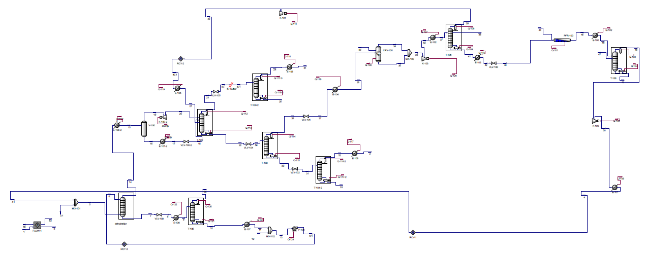
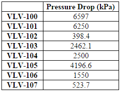
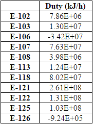
The design described above was simulated in Aspen HYSYS to determine necessary stream specifications, required utilities and sizing information for the various pieces of equipment for this process. A picture of the setup in HYSYS and details of the HYSYS results, including stream and equipment specifications, can be found in Appendices C |
The design described above was simulated in Aspen HYSYS to determine necessary stream specifications, required utilities and sizing information for the various pieces of equipment for this process. A picture of the setup in HYSYS and details of the HYSYS results, including stream and equipment specifications, can be found in Appendices C and D. |
||
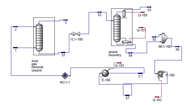
The fluid package used for the main case of the simulation was Peng-Robinson (PR) which was chosen because it is most compatible with hydrocarbons (National Technical Institute of Athens). However, PR is not compatible with the absorbent, diethylamine (DEA), that is required in the acid gas removal portion of the process. Thus, it was necessary to simulate the acid gas removal (CO2 absorption column & DEA recovery distillation column) in a sub-flowsheet that utilizes the amine fluid package (National Technical Institute of Athens). All other processes were simulated within the main case. |
The fluid package used for the main case of the simulation was Peng-Robinson (PR) which was chosen because it is most compatible with hydrocarbons (National Technical Institute of Athens). However, PR is not compatible with the absorbent, diethylamine (DEA), that is required in the acid gas removal portion of the process. Thus, it was necessary to simulate the acid gas removal (CO2 absorption column & DEA recovery distillation column) in a sub-flowsheet that utilizes the amine fluid package (National Technical Institute of Athens). All other processes were simulated within the main case. |
||
| Line 54: | Line 63: | ||
The reactor is modeled as a PFR (R-101) in HYSYS. Before entering the cracking reactor, the inlet is heated to 825 C using HPS (E-121) and passed through a valve (V-105) to reduce the pressure to 300 kPa because steam cracking must occur at high temperatures and low pressures in order to be effective (Sims, 1999). This stream then enters the reactor along with 12,600 kg/hr of steam at 300 kPa, to dilute the hydrocarbon stream and prevent coking. The reactor is modeled using the five reactions as listed below. The exact parameters for these reactions can be found in “Modeling of Thermal Reactor Kinetics” by Sundaram and Froment (Sundaram and Froment, 1997). |
The reactor is modeled as a PFR (R-101) in HYSYS. Before entering the cracking reactor, the inlet is heated to 825 C using HPS (E-121) and passed through a valve (V-105) to reduce the pressure to 300 kPa because steam cracking must occur at high temperatures and low pressures in order to be effective (Sims, 1999). This stream then enters the reactor along with 12,600 kg/hr of steam at 300 kPa, to dilute the hydrocarbon stream and prevent coking. The reactor is modeled using the five reactions as listed below. The exact parameters for these reactions can be found in “Modeling of Thermal Reactor Kinetics” by Sundaram and Froment (Sundaram and Froment, 1997). |
||
:<math>C_2H_6 \rightleftharpoons C_2H_4 + H_2</math> |
'''Equation 1''' :<math>C_2H_6 \rightleftharpoons C_2H_4 + H_2</math> |
||
:<math>2C_2H_6 \to C_3H_8 + CH_4</math> |
'''Equation 2''' :<math>2C_2H_6 \to C_3H_8 + CH_4</math> |
||
:<math>C_3H_6 \rightleftharpoons C_2H_2 + CH_4</math> |
'''Equation 3''' :<math>C_3H_6 \rightleftharpoons C_2H_2 + CH_4</math> |
||
:<math>2C_2H_2 + C_2H_4 \to C_4H_6</math> |
'''Equation 4''' :<math>2C_2H_2 + C_2H_4 \to C_4H_6</math> |
||
:<math>2C_2H_4 + C_2H_6 \to C_3H_6 + CH_4</math> |
'''Equation 5''' :<math>2C_2H_4 + C_2H_6 \to C_3H_6 + CH_4</math> |
||
The extent of each of these reactions can be found in Table B.5. Overall, ethane goes from 58% in the inlet stream to 18% in the outlet (after quenching) while ethylene increases from 35% to 48%. The reactor operates isothermally and therefore must be heated with high pressure steam. The duty required for the reactor is 1.22E8 kJ/hr. |
The extent of each of these reactions can be found in Table B.5. Overall, ethane goes from 58% in the inlet stream to 18% in the outlet (after quenching) while ethylene increases from 35% to 48%. The reactor operates isothermally and therefore must be heated with high pressure steam. The duty required for the reactor is 1.22E8 kJ/hr. |
||
| Line 111: | Line 120: | ||
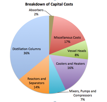
[[File:Cc.PNG|thumb|upright=1.5|'''Figure 1:''' Breakdown of Total Capital Costs ]] |
[[File:Cc.PNG|thumb|upright=1.5|'''Figure 1:''' Breakdown of Total Capital Costs ]] |
||
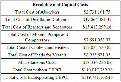
The total capital cost of the plant sums to $119,741,168.46. This value includes the cost of equipment as well as installation costs (calculated using Hand’s Method), miscellaneous costs for piping, tees, storage tanks, and other fittings. A 25% contingency cost was added to the cost of vessels to account for the cost and installation of vessel heads. Materials of construction was also an important consideration in the calculation, as the demethanizer and the ethylene splitter required austenitic stainless steel due to low temperatures. For each of the columns, diameter was determined by the tray sizing or pressure vessel sizing utilities in HYSYS, the height was determined by calculating the number of trays and a thickness was calculated on checalc.com, based on design temperature and pressure. Knowing these measurements, a volume can be calculated and using the density of the material of construction, |
The total capital cost of the plant sums to $119,741,168.46. This value includes the cost of equipment as well as installation costs (calculated using Hand’s Method), miscellaneous costs for piping, tees, storage tanks, and other fittings. A 25% contingency cost was added to the cost of vessels to account for the cost and installation of vessel heads. Materials of construction was also an important consideration in the calculation, as the demethanizer and the ethylene splitter required austenitic stainless steel due to low temperatures. For each of the columns, diameter was determined by the tray sizing or pressure vessel sizing utilities in HYSYS, the height was determined by calculating the number of trays and a thickness was calculated on checalc.com, based on design temperature and pressure. Knowing these measurements, a volume can be calculated and using the density of the material of construction, equation 6 is used to calculate cost of material. |
||
:<math>C = a + b*S^n</math> (Equation 6) (Towler et at., 2013) |
|||
'''Equation 6''' :<math>C = a + b*S^n</math> (Towler et at., 2013) |
|||
Figure 1 depicts the breakdown of total capital costs. The distillation columns contained a large percentage of the capital costs because the demethanizer and ethylene splitter required cryogenic technology. Other notable expenses included miscellaneous costs (about a 17% contingency cost of the total capital cost), reactors and separators (14%) and coolers and heaters (16%). |
Figure 1 depicts the breakdown of total capital costs. The distillation columns contained a large percentage of the capital costs because the demethanizer and ethylene splitter required cryogenic technology. Other notable expenses included miscellaneous costs (about a 17% contingency cost of the total capital cost), reactors and separators (14%) and coolers and heaters (16%). |
||
==Energy Usage== |
==Energy Usage== |
||
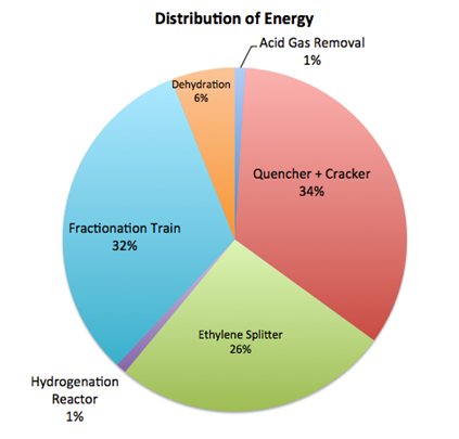
[[File:Energy.PNG|thumb|left|upright=1.5|'''Figure 2:''' Breakdown of Energy Costs]] |
|||
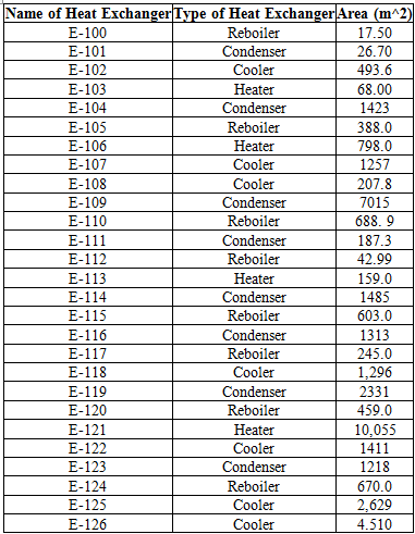
An important aspect of the plant is the energy usage. In order to determine energy usage of the plant, the heat exchanger areas of the condensers, reboilers, coolers and heaters must be calculated. To do so, Aspen Energy Analyzer was used, calculating heat exchanger areas ranging from 4.5 to 10,000 m2 (for a more comprehensive list of heat exchanger areas, refer to Table D.8). The size of the smaller areas were due to the more simple tasks of cooling and heating. However, for areas that ranged from 7000-10,000 m2, these heat exchangers were large because some streams needed to be cooled to extremely low temperatures for cryogenic separation, which required more energy and thus, required a larger heat exchanger area. |
|||
Figure 2 displays the breakdown of energy usage, including heat exchangers, condensers, pumps, and other equipment. The areas with the highest energy usage are the cracking reactor with the quencher (34%), the fractionation train (32%) and ethylene splitter (26%). The high cracking reactor energy usage is as to be expected because it requires very high temperatures. The fractionation train and ethylene splitter require a lot of energy because both of these systems contains cryogenic separation. |
|||
==Fixed and Variable Costs== |
==Fixed and Variable Costs== |
||
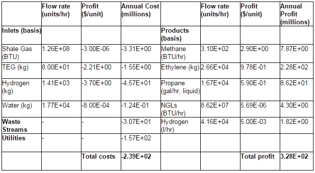
Table E.2 in Appendix E lists the variable costs and profits. Variable costs consist of the price of inlet streams, treatment of the waste streams and utilities. The inlet streams are shale gas, TEG for the dehydration section, hydrogen for the hydrogenation reactor, and water. The prices of these inlets were determined from market values or best available estimates (EIA- Natural Gas Weekly Update)(NREL)(Alibaba)(Shanbhag et al.). The cost of waste treatment corresponds to the estimated amount for offsite treatment of organic waste (Northwestern University ChE 351 notes). Utilities are comprised of the necessary heating and cooling for the various heat exchangers as well as the electricity for pumps and compressors. These were determined from the HYSYS simulation and Aspen Energy Analyzer. The total variable costs are about $239 million/year. Variable profits come from the sale of products, which are methane, ethylene, propane, NGLs, and hydrogen. Prices for these products were determined from current market values and trends (EIA)(Index Mundi)(EIA-NYMEX)(Platts Global Petrochemical Index)(HES Hydrogen RSS). The total profit from the sales of all the product streams is $328 million annually. |
|||
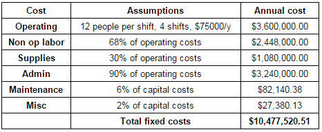
The fixed costs of the process include costs of operation, administration, supplies, maintenance, and other miscellaneous expenses such as insurance and taxes. To calculate operating costs, it was assumed that the there would be 12 people per shift, with 4 shifts, and that each operator makes $75,000/yr. This assumption was made because it allows approximately one operator per major piece of equipment. The remaining fixed costs were estimated as a certain percentage of this total operating costs (Northwestern University ChE 351 notes). The total fixed costs sum to be about $10.5 million/year. The breakdown of the fixed costs and the assumptions made for each calculation are shown in Table E.3 of the appendix. |
|||
==Overall Economic Feasibility== |
==Overall Economic Feasibility== |
||
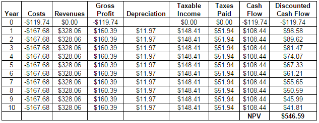
A 10-year net present value (NPV) was calculated. The following assumptions were made for the NPV calculation: depreciation was calculated as 10-year straight line depreciation, a 35% corporate tax rate, and a 10% time discount rate. The 10 year NPV is $547 million. Additionally, the project has a payback period of 3 years and an internal rate of return (IRR) of 72%. The full NPV calculation spreadsheet can be found in Appendix E. All of these economic indicators are good, which indicate that the project should be pursued. |
|||
==Sensitivity Analysis== |
==Sensitivity Analysis== |
||
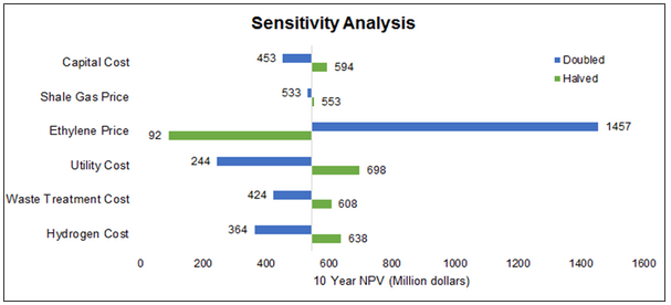
A basic sensitivity analysis was conducted by changing the cost of several key parameters and evaluating the change in the 10 year NPV. Six parameters were evaluated and the results are displayed in Figure 3. The parameter with the largest effect is the price at which ethylene can be sold. This is reasonable, as ethylene is the most valuable product. From this, it can also be inferred that changing pricing in the other products will have less of an effect than ethylene price. Two inlet prices were analyzed: shale gas and hydrogen. Shale gas had very little effect, however, this is likely because the current price of shale gas is extremely low, so much so that even when it is doubled it remains very low. Shale gas has the potential to increase well beyond doubling, which could have a larger effect on NPV. Hydrogen was analyzed because it is the largest fraction of inlet costs. As seen, this has a bigger effect than the price of shale gas. Capital cost was evaluated because it is among the most uncertain of all the economic components calculated. However, even when doubled, the NPV remains positive. Changing waste treatment cost and utility costs were also evaluated as these are dictated by companies outside of the plant’s control and could feasibly change. Note that for all parameters evaluated, the NPV remains positive, which provides a good outlook for the project. |
|||
[[File:Sens.PNG|frame|center|'''Figure 3:''' Sensitivity Analysis]] |
|||
=Conclusion and Recommendations= |
=Conclusion and Recommendations= |
||
The project is very viable from an economics standpoint as determined by all three common economic measures calculated (NPV, IRR, and payback period). However, this report has not addressed safety, health, and environmental concerns. Before the project proceeds, these should be analyzed. Of particular concern is the operating temperatures of the cryogenic distillation columns. The coolers of the demethanizer, methane/H2 splitter, and ethylene splitter are all around or below -100C. While theoretically feasible to operate an exchanger at these temperatures using special cryogenic refrigerants, it is difficult and could pose a safety hazard. Therefore, we recommend that a thorough safety analysis be conducted before proceeding. Additionally, the profitability of this process is highly contingent on the price of ethylene, which has plummeted recently. Thus, conducting a thorough market analysis on the future price of ethylene is advised. |
|||
=References= |
=References= |
||
Alibaba. Diethylamine Price (n.d.). Available at: http://www.alibaba.com/showroom/diethylamine-price.html |
|||
Alkhudhiri A, Darwish N, Hilal N. "Membrane Distillation: A Comprehensive Review." Desalination. 2012; 287: 2-18. |
|||
American Petroleum Institute. “VOC Content Threshold for Reduced Emissions Completions.” Published March 2, 2011. Available at: http://www.whitehouse.gov/sites/default/files/omb/assets/oira_2060/2060_03222012-2.pdf. |
|||
American Petroleum Institute. VOC Content Threshold for Reduced Emissions Completions. Published March 2, 2011. Available at: http://www.whitehouse.gov/sites/default/files/omb/assets/oira_2060/2060_03222012-2.pdf. |
|||
Dow. “Gas Sweetinging”. Published 1998. Available at: http://msdssearch.dow.com/PublishedLiteratureDOWCOM/dh_0039/0901b803800391f8.pdf?filepath=gastreating/pdfs/noreg/170-01395.pdf&fromPage=GetDoc. |
|||
Ethylene Gas Specifications. Advanced Specialty Gases Website. Published 2014. Available at: http://www.advancedspecialtygases.com/Ethylene.html. |
|||
Forde T. Drying of Natural Gas. Aker Solutions. Available at:http://www.ipt.ntnu.no/~jsg/undervisning/naturgass/lysark/LysarkFoerde2008.pdf. Published September 10, 2008. |
|||
Gao GY, Wang M, Ramshaw C , Li XG, Yeung H. Optimal operation of tubular reactors for naphtha cracking by numerical simulation. Asia-Pacific Journal of Chemical Engineering, 2009; 4(6): 885-892. Available at: https://dspace.lib.cranfield.ac.uk/bitstream/1826/4226/1/tubular_reactors_for_naphtha_cracking-2009.pdf |
|||
Gas Separation Technology LLP. "Pressure Swing Adsorption." 2013. Available at: http://www.gassep.com/PSA.htm. |
|||
Getua M, Mahadzir S, Van Duc Long N, Lee M. Techno-economic analysis of potential natural gas liquid (NGL) recovery processes under variations of feed compositions. Chemical Engineering Research and Design. 2013; 91: 1272-1283.http://dx.doi.org/10.1016/j.cherd.2013.01.015 |
|||
HES Hydrogen RSS. Hydrogen Fuel Cost vs Gasoline. Available at:http://heshydrogen.com/hydrogen-fuel-cost-vs-gasoline/ |
|||
Index Mundi. Propane Daily Price, Feb 23, 2015. Available at: http://www.indexmundi.com/commodities/?commodity=propane |
|||
Keller A. NGL 101 - The Basics. EIA Website. Published June 6, 2012. Available at: http://www.eia.gov/conference/ngl_virtual/eia-ngl_workshop-anne-keller.pdf. |
|||
Khan N.A., Shaikhutdinov S., Freund H.J., “Acetylene and ethylene hydrogenation on alumina supported Pd-Ag model catalysts.” Catalysis Letters. 108, 159 (2006). Available at: http://w0.rz-berlin.mpg.de/hjfdb/pdf/442e.pdf |
|||
Klinkenbijl, J. Dillon, M, Heymen, E. Gas Pre-treatment and their Impact on Liquefaction Processes. Published March 2, 1999. Available at:http://iptibm1.ipt.ntnu.no/~jsg/undervisning/naturgass/dokumenter/GasPreTreatment.pdf. |
|||
Lee SH. Partial catalytic hydrogenation of acetylene in ethylene production. Johor, Malaysia: KLM Technology Group, 2004. Retrieved from: http://www.klmtechgroup.com/PDF/Articles/articles/acetylene_converter.pdf |
|||
National Renewable Energy Laboratory (NREL). Hydrogen Production Cost Analysis (n.d.) Available at: http://www.nrel.gov/hydrogen/production_cost_analysis.html |
|||
National Technical Institute of Athens. “Aspen HYSYS-Fluid Package Selection.” Available at: ecourses.chemeng.ntua.gr/tools/getfile.php?file=516&type=file |
|||
Nivargi J.P., Gupta D.F., Shaikh S.J., Shah K.T., “TEG Contactor for Gas Dehydration.” Chem.Eng World, 40 (9) (2005), pp. 77–80. Available at: http://www.fenixchemtech.in/pdf/teg_contactor.pdf |
|||
Northwestern University ChE 351 notes, Fall 2014. Prof. Harold Kung, TA M. Alexander Ardagh. |
|||
OLI Systems, Inc. “Flowsheet Simulation Application Brief: Gas Sweetening using DEA.” Available at: http://support.olisystems.com/ApplicationBriefs/Briefs%20-%20Gas%20Sweetening%20using%20DEA.pdf |
|||
Platts Global Petrochemical Index. Platts Global Ethylene Price Index, 2014. Available at: http://www.platts.com/news-feature/2014/petrochemicals/pgpi/ethylene |
|||
Praxair. Buying Ethylene, MSDS and Spec Sheet. Available at: http://www.praxair.com/gases/buy-ethylene |
|||
Shanbhag N.G., America H. Compressed Air Best Practices. Calculating the Water Costs of Water-Cooled Air Compressors - Part 1 (n.d.) Available at:http://www.airbestpractices.com/technology/air-compressors/calculating-water-costs-water-cooled-air-compressors-part-1 |
|||
Shell Global Solutions. Sulfinol-M. Shell Website. Published 2012. Available at:http://s02.static-shell.com/content/dam/shell/static/globalsolutions/downloads/services/sulfino-m.pdf. |
|||
Sims DW. Pre-fractionating the feedstock to separate into an ethane rich stream and a propane rich stream, steam cracking each stream to form ethylene. 1999, US5990370 A. http://www.google.com/patents/US5990370 |
|||
Sundaram, KM, Froment, KF. “Modeling of thermal cracking kinetics—I: Thermal cracking of ethane, propane and their mixtures.” Chemical Engineering Science. 1997; 32 (6): 601-608. doi:10.1016/0009-2509(77)80225-X. |
|||
Towler G, Sinnott R. Chemical Engineering Design: Principles, Practice and Economics of Plant and Process Design. 2nd ed. Boston: Elsevier; 2013. |
|||
Transform Software and Services. “A Comparative Study of North America's Largest Shale Gas Reservoirs.” Available at: https://www2.transformsw.com/joomla/index.php?option=com_content&view=article&id=67&Itemid=82 |
|||
U.S. Energy Information Administration (EIA). Natural Gas Futures Prices (NYMEX), Feb. 25 2012. Available at: http://www.eia.gov/dnav/ng/ng_pri_fut_s1_m.htm |
|||
U.S. Energy Information Administration (EIA). Natural Gas Weekly Update, Feb 26, 2015. Available at: http://www.eia.gov/naturalgas/weekly/ |
|||
Woebcke, HN. Process for pyrolysis of hydrocarbons. 1993, US5271827 A. Available at: https://courses.northwestern.edu/webapps/portal/frameset.jsp?tab_tab_group_id=_2_1&url=%2Fwebapps%2Fblackboard%2Fexecute%2Flauncher%3Ftype%3DCourse%26id%3D_429745_1%26url%3D |
|||
=Appendices= |
=Appendices= |
||
==Appendix A: Shale Gas Composition== |
==Appendix A: Shale Gas Composition== |
||
| Line 133: | Line 236: | ||
==Appendix C: HYSYS Diagram== |
==Appendix C: HYSYS Diagram== |
||
[[File: |
[[File:HSYYSfull.png|frame|none|'''Figure C.1:''' Main Flowsheet]] |
||
[[File: |
[[File:HYSYSamine.png|frame|none|'''Figure C.2:''' Sub-Flowsheet]] |
||
==Appendix D: Equipment List== |
==Appendix D: Equipment List== |
||
[[File:D1.PNG|frame|none|'''Table D.1:''' Distillation Columns Data]] |
[[File:D1.PNG|frame|none|'''Table D.1:''' Distillation Columns Data]] |
||
[[File:D2.PNG|frame|none|'''Table D.2:''' Absorbers Data]] |
[[File:D2.PNG|frame|none|'''Table D.2:''' Absorbers Data]] |
||
[[File:D3.PNG|frame|none|'''Table D.3:''' Separator Data ]] |
[[File:D3.PNG|frame|none|'''Table D.3:''' Separator Data ]] |
||
[[File:D4.PNG|frame|none|'''Table D.4:''' Reactor Data]] |
[[File:D4.PNG|frame|none|'''Table D.4:''' Reactor Data]] |
||
[[File:D5.PNG|frame|none|'''Table D.5:''' Pumps, Expanders, Compressors Data]] |
[[File:D5.PNG|frame|none|'''Table D.5:''' Pumps, Expanders, Compressors Data]] |
||
[[File:D6.PNG|frame|none|'''Table D.6:''' Valve Data ]] |
[[File:D6.PNG|frame|none|'''Table D.6:''' Valve Data ]] |
||
[[File:D7.PNG|frame|none|'''Table D.7:''' Heater and Condensers Data ]] |
[[File:D7.PNG|frame|none|'''Table D.7:''' Heater and Condensers Data ]] |
||
[[File:D8.PNG|frame|none|'''Table D.8:''' Heat Exchanger Area]] |
[[File:D8.PNG|frame|none|'''Table D.8:''' Heat Exchanger Area]] |
||
| Line 159: | Line 276: | ||
[[File:F1.PNG|frame|none|'''Table E.1:''' Capital Costs]] |
[[File:F1.PNG|frame|none|'''Table E.1:''' Capital Costs]] |
||
[[File:F2.PNG|frame|none|'''Table E.2:''' Variable Costs]] |
[[File:F2.PNG|frame|none|'''Table E.2:''' Variable Costs]] |
||
[[File:F3.PNG|frame|none|'''Table E.3:''' Fixed Costs]] |
[[File:F3.PNG|frame|none|'''Table E.3:''' Fixed Costs]] |
||
[[File:F4.PNG|frame|none|'''Table E.4:''' NPV calculations]] |
[[File:F4.PNG|frame|none|'''Table E.4:''' NPV calculations]] |
||
Latest revision as of 20:08, 13 March 2015
Team G2 Final Report
Authors: Katie Johnson, Michelle Spiezio, Tammy Wong
Instructors: Fengqi You, David Wegerer
March 13, 2015
Executive Summary
This report is part of an ongoing project to design a process to produce ethylene and NGLs from shale gas. The inlet raw shale gas is taken from the Barnett Shale site in Texas with an inlet flow rate of shale is 171,200 kg/hr. The design would be implemented in Johnson County, TX, which is nearby the shale site. The Barnett shale contains about 17% ethane, which we seek to separate from the inlet gas and convert into ethylene via steam cracking. Additionally, because the shale contains significant amounts of other hydrocarbons, natural gas, propane, and NGLs will be recovered from the shale to be sold.
The proposed design consists of six main sections which were modeled in HYSYS: acid gas removal, dehydration, fractionation train, hydrogenation reactor, ethylene splitter, and steam cracking. The acid gas removal section uses Diethylamine (DEA) to remove the CO2 from the raw shale gas. The DEA is fully recovered, thus no make-up stream is required, and the CO2 content is reduced from 0.66 to 0.04 mol%. The purpose of the dehydration section is to remove all of the water from the shale before it is sent through the fractionation train, as water will freeze due to the low temperatures in this section. Triethylene glycol (TEG) is used to absorb water from the gas, reduce the water content from 2.44 to 0.01 mol%. TEG is then partially recovered and recycled. The fractionation train consists of 4 distillation columns. The first is the demethanizer, which yields a methane-rich tops that is sent to a second distillation column to purify methane for sale, and the bottoms is sent to the third column, the deethanizer. The deethanizer ethane-rich tops is sent on for further processing, while the bottoms is sent to the fourth column, the depropanizer, with yields a propane top stream and an NGL bottom stream. The next section is the hydrogenation reactor, into which the tops of the deethanizer is fed to selectively hydrogenate acetylene, which is an impurity from the cracking reactor, into ethylene and ethane, reducing the content of acetylene in the gas from 100 ppm to 4 ppm. Next, they hydrogenated gas proceeds to an ethylene splitter which separates ethylene for sale, methane to recycle, and ethane which proceeds to the final section, the cracking reactor. The cracking reactor operates at about 820C and converts ethane to ethylene, with the cracked gas containing 48% ethylene. The cracked gas is then quenched and recycled for purification.
This discussed design results in the following product streams: 26,600 kg/hr of >98% purity ethylene , 6,300 kg/hr of 94% pure hydrogen, 68,600 kg/hr of 96% pure methane, 30,600 kg/hr of 97% pure propane, and 38,200 kg/hr of NGLs, which is 72% butane and 26% pentane. The total profits from the sale of these products surmounts to about $328 million annually. The annual cost of this design includes the cost of purchasing feeds, offsite organic waste treatment, utilities (determined from Aspen Energy Analyzer), labor, and other miscellaneous costs. This annual cost is $250 million. Additionally, the total capital cost, determined from estimated equipment sizes as well as added contingency for piping and other fixtures, sums to $120 million. From these costs, the design has a 10 year NPV of $547 million, a payback period of 3 years and an internal rate of return (IRR) of 72%. These calculations indicate a profitable design that should be pursued. However, this design and the resulting calculations should be refined with additional researching and alternatives beyond what is presented in this report.
Introduction
This report summarizes a project to design a process to produce ethylene and NGLs from shale gas. The production of ethylene is desirable because ethylene is a valuable product in the production of polymers, chemicals and other consumer products. In this final report, the design and simulation in HYSYS are discussed in detail. In addition, the rationale behind the selection of the specific technology chosen for the design is provided. The objectives when choosing specific technology were to maximize efficiency and conversion while minimizing capital and operating costs of the facility. Finally, an economic analysis was conducted, including capital costs, variable costs and fixed costs analyses with an overall NPV calculation. Additionally, a sensitivity analysis was conducted to determine the effect of certain design tradeoffs and changes in market pricing.
Technical Approach
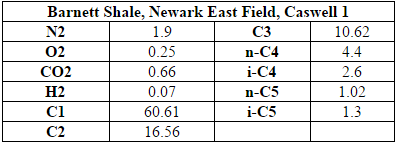
The inlet to the process is raw shale gas that is taken from the Barnett Shale site in Texas (specifically, shale gas extracted from well C1 of the Newark East field). The inlet flow rate of shale is 171,200 kg/hr and the composition of this raw shale gas is shown in Table A.1 of the appendix (American Petroleum Institute, 2011). It is assumed that there is little to no sulfur in the raw shale gas. The plant will be located nearby in Johnson County, Texas. This location is near the extraction site of the Barnett shale gas to avoid large transportation distances and costs but far enough away from the Dallas-Ft. Worth area to ensure adequate land availability and privacy.
While ethylene is the only product chemically produced, hydrogen, methane, propane, and NGLs are recovered in the process and can be sold. To be sold, the following purities must be met or exceeded: 98% pure ethylene, 90% pure hydrogen, 95% pure methane and propane, and 95% purity NGLs (Ethylene Gas Specifications, 2014 and Keller, 2012). Thus, the approach taken in the development of this design is to take raw inlet shale, refine it to separate out methane, ethane, propane and NGLs and then use the ethane to produce ethylene via steam cracking. Further processing and refinement also leads to the recovery of hydrogen (an input added to the hydrogenation reactor and produced in the steam cracking process).
Design Summary
Overview
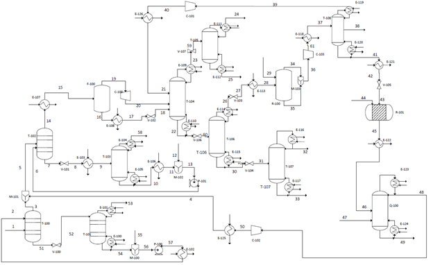
The proposed design consists of six main sections: acid gas removal, dehydration, fractionation train, hydrogenation reactor, an ethylene splitter and steam cracking (refer to Appendix B for the process flow diagram). Carbon dioxide must first be removed from the inlet shale gas in the acid gas removal section. This is accomplished using an absorption column. The resulting shale gas is termed “sweet gas”. The sweet gas is then mixed with cracking gas from another part of the plant before it is sent to another absorption column so that water can be removed. This dehydrated stream is then sent onto the fractionation train, where it is cooled then sent through a series of cryogenic distillation columns to separate out methane, ethane, and propane. The methane stream is further refined to separate out methane from light gases (H2, O2, and N2). The ethane stream continues on to the rest of the process. It contains a small amount of acetylene (a product of the cracking reactor) which is removed in a hydrogenation reactor. After the acetylene is removed, the stream is then sent to another cryogenic distillation column, the ethylene splitter. The splitter recovers methane which is recycled back to the demethanizer. Additionally, a side draw separates out ethylene which is to be sold. The remaining stream, consisting mostly of ethane, is fed into a cracking reactor with steam to produce ethylene. After exiting the reactor, it is quenched to stop the reaction. This stream is then recycled and combined with the sweet gas so that it can be purified.
HYSYS Simulation
The design described above was simulated in Aspen HYSYS to determine necessary stream specifications, required utilities and sizing information for the various pieces of equipment for this process. A picture of the setup in HYSYS and details of the HYSYS results, including stream and equipment specifications, can be found in Appendices C and D.
The fluid package used for the main case of the simulation was Peng-Robinson (PR) which was chosen because it is most compatible with hydrocarbons (National Technical Institute of Athens). However, PR is not compatible with the absorbent, diethylamine (DEA), that is required in the acid gas removal portion of the process. Thus, it was necessary to simulate the acid gas removal (CO2 absorption column & DEA recovery distillation column) in a sub-flowsheet that utilizes the amine fluid package (National Technical Institute of Athens). All other processes were simulated within the main case.
Acid Gas Removal
The first step in the process is the removal of carbon dioxide from the inlet shale gas. This is done with an absorption column with DEA as the absorbent. The inlet shale gas is fed into the absorption column, T-100, at a flow rate of 171,200 kg/hr, at 6900 kPa (1000psi) and around 50C (Transform Software and Services). The composition of the inlet shale is shown in Table 1 of the Appendix A (American Petroleum Institute, 2011). Recycled aqueous diethylamine is fed into the column at similar temperature and pressure (Oli Systems, Inc.). The vapor exiting the top of the column is the shale gas without CO2 and comes out the column at 170,000 kg/hr, with a temperature of around 55C and pressure of 6700 kPa. The absorber reduces the CO2 component fraction in the shale gas from 0.66 to 0.04 mol%.
The bottoms, the spent DEA, exit from the column at 32,400 kg/hr at a temperature around 50C and pressure of 6800 kPa. The spent DEA is sent through a distillation column, T-101, in order to regenerate the DEA and minimize material cost. However, the pressure of the spent DEA must first be brought down to 202 kPa for distillation to be viable.7 The distillate is CO2 vapor and the bottoms are recovered DEA. The bottoms are mixed with 900 kg/hr makeup water to compensate for water loss in the tops, pumped back up to 6895 kPa, and then reenter the absorption column. All of the DEA is recovered. The distillation column reduces the CO2 component fraction in the DEA stream from 4.73 to 0.93 mol%.
Dehydration
After exiting T-100, the sweet gas is mixed with the recycled cracking gas and fed into the dehydration absorption column, T-102, along with triethylene glycol (TEG) to absorb the water. The gas comes in at a rate of 271,000 kg/hr and the TEG at a rate of 39,800 kg/hr, both with a temperature around 53C and pressure of 6700 kPa. T-102 reduces the water component fraction of the sweet gas from 2.44 to 0.01 mol%. The distillate of T-102 is the dehydrated gas and the bottoms is the spent TEG. The dehydrated gas exits at 266,000 kg/hr at a temperature of 57C and pressure of 6550 kPa.
The spent TEG comes out at a rate of 45,100 kg/h, with a temperature of 58C and pressure of 6650 kPa. The pressure of the TEG is then reduced to 400 kPa and the temperature is increased to 150C in order to prepare it for distillation.8 The amount of water in the TEG stream is reduced from 49.16 to 1.03 mol%. The tops of T-103 is mostly water vapor and the bottoms is the recovered TEG that is then cooled, mixed with additional pure TEG to compensate for losses in the overhead, and then pumped back up to pressure before being recycled into absorption column T-102. Although these temperature and pressure changes require excess energy, recovery of TEG using distillation is only viable at the lower pressure and higher temperature specified above in order to prevent the degradation of TEG (Nivargi, Gupta, Shaikh and Shah, 2005).
Fractionation Train
After the dehydration process the gas is sent through the fractionation train, which is a series of distillation columns used to separate out the various hydrocarbons in the stream. The HYSYS simulation was modeled after a combination of the industry standard single stage (ISS) process and gas subcooled process (GSP). After dehydration, the stream is first cooled from 57C to -10C to prepare the stream for fractionation distillation. This causes the heavier components of the inlet gas to become liquid and lighter components to remain gas. This gas/liquid stream is fed into a flash separator (F-100), which separates the the heavier hydrocarbons from the lighter components. The gas stream that leaves the top of the flash separator is fed into a turboexpander (C-100) for further cooling. The liquid stream that leaves the bottom of the flash separator is further cooled through a cooler (E-108) and a Joule Thompson Valve (V-102). Both the streams enter the demethanizer column (T-104) along with a recycle stream from the ethylene splitter. It should be noted that the methane recycle is fed into a low stage, the liquid stream is fed into a higher stage, and the vapor stream is fed into the highest stage in order to maximize separation of ethane and the NGLs.
The demethanizer is a cryogenic distillation column. The distillate is a combination of methane and the lighter gases such as hydrogen, oxygen, and nitrogen gas. This stream is then sent to another distillation column (T-105) that contains 10 trays to separate the light gases from the methane. The distillate from T-105 contains 6% nitrogen and 88% hydrogen while the bottoms product has a composition of predominantly methane (98%). Both of these streams can be sold as products.
The bottoms of the demethanizer is predominantly composed of ethylene (41%), propane (13%) and ethane (35%). This stream is sent to the deethanizer, another distillation column (T-106). The distillate from the deethanizer has a composition of 54% ethylene and 46% ethane and is sent onto the hydrogenation reactor (R-100) while the bottoms contains approximately 53% propane, 35% butane and 11% pentane and is sent to the depropanizer (T-107). The bottoms of the deethanizer go through a valve which reduce the temperature from 120C to 64C and reduce the pressure from 2850 kPa to 1300 kPa. This stream is then sent into the depropanizer. The depropanizer contains a distillate product of predominantly propane (97%) and a bottoms product of 24% pentane and 73% of butane.
Hydrogenation Reactor
The tops coming from the deethanizer column contains mostly ethane and ethylene along with smaller amounts of methane and acetylene (specific compositions can be found in Table E.2). This stream is intended for further separation to remove the ethylene product, but acetylene must first be removed, as it cannot be in the final product (Lee, 2004). To remove this acetylene, a hydrogenation reactor with a palladium catalyst is used to selectively convert the acetylene to ethylene and ethane. This catalyst was chosen because of the high selectivity for and conversion of acetylene combined with a low conversion of ethylene to ethane (Lee, 2004)
The tops of the deethanizer has a flow rate of 127,000 kg/hr and contains 100 ppm of acetylene. Before entering the hydrogenation reactor, the stream is first sent through a valve (V-103) to reduce the pressure to around 11 bar and then heated (E-113) to 20C. This is done because the reactor must operate at lower pressures and higher temperatures than the fractionation train ( In addition to the ethane mix stream, 1,410 kg/hr of pure hydrogen is added to allow the reaction to occur. The dehydrogenation reactor was modeled using a conversion reactor in HYSYS. There are two reactions in the reactor: acetylene to ethylene, which has a conservative 90% conversion, and acetylene to ethane, which has a 5% conversion (Khan, Shaikhutdinov, Freund, 2006). The reactor is extremely exothermic with a duty of -100 kJ/hr and is assumed to run isothermally (Table D.4 in Appendix D contains details on the specific reactor conditions and conversions). Note that the energy produced in the reactor can be used to heat water or steam, which can then be used to heat the inlet stream of the reactor. The outlet stream is vapor at 17 C and 655 kPa with a flow rate of 128,000 kg/hr and an acetylene content of 4 ppm. This stream contains 42.5% ethylene, the desired product, and is cooled then sent to the ethylene splitter.
Ethylene Splitter
After exiting the dehydrogenation reactor, the product stream is cooled to -80C. It is then fed into stage 15 of a 17-tray distillation column. This stream is fed in at such a low stage in order to maximize the purity of the ethylene recovery. Ethylene is removed from a liquid side draw at tray 2 at at rate of 28,100 kg/hr and a purity of 98.9%. This is above the desired 98% purity specified in the design basis. Because this stream emerges as a cold liquid at around 10 bar, it can then be transported and sold immediately without any additional treatment (Praxair). The distillate of this column is a vapor consisting mostly of methane and hydrogen. This stream is compressed back up to 3000 kPa, cooled to -50C, and then recycled back into the inlet of the demethanizer. The bottoms of the ethylene splitter consist of 38% ethylene, 62% ethane, and <0.5% propane. This stream is then sent to the cracking reactor.
Steam Cracking
After the ethane leaves the ethylene splitter, it is fed into a cracking reactor along with steam to dilute the ethane stream and prevent carbonization. The cracking reactor is comprised of three sections. The first two sections are used to increase the ethane temperature with convection coils to around 650C and to introduce the steam (Sims, 1999). The third section is the radiative section where the gas enters tubes which are then exposed to radiant heat to rapidly bring the temperature of the ethane up to around 820C to induce cracking, which occurs for less than a second (Gao, Wang, Ramshaw, Li and Yeung, 2009).
The reactor is modeled as a PFR (R-101) in HYSYS. Before entering the cracking reactor, the inlet is heated to 825 C using HPS (E-121) and passed through a valve (V-105) to reduce the pressure to 300 kPa because steam cracking must occur at high temperatures and low pressures in order to be effective (Sims, 1999). This stream then enters the reactor along with 12,600 kg/hr of steam at 300 kPa, to dilute the hydrocarbon stream and prevent coking. The reactor is modeled using the five reactions as listed below. The exact parameters for these reactions can be found in “Modeling of Thermal Reactor Kinetics” by Sundaram and Froment (Sundaram and Froment, 1997).
Equation 1 :
Equation 2 :
Equation 3 :
Equation 4 :
Equation 5 :
The extent of each of these reactions can be found in Table B.5. Overall, ethane goes from 58% in the inlet stream to 18% in the outlet (after quenching) while ethylene increases from 35% to 48%. The reactor operates isothermally and therefore must be heated with high pressure steam. The duty required for the reactor is 1.22E8 kJ/hr.
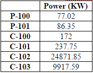
After exiting the reactor, the product is cooled to 400 C in a heat exchanger (E-122) then mixed with cooling water in a quencher. In HYSYS, the quencher is modeled with a distillation column, allowing both the temperature changes and the contact between the water and inlet to be modeled.The bottoms from this column is waste water, which is sent for off-site treatment. The distillate is then compressed (C-102) back up to 6750 kPa and cooled to 50 C (E-125) before being recycled and mixed with the inlet to the dehydration section to undergo purification.
Process Optimization
The process was optimized in several ways in order to minimize total cost. The reflux ratio and number of trays in each of the distillation columns were optimized to reduce the capital cost of the column while still meeting the required purity specifications. Utility usage was minimized by operating at each column at as high of a pressure as possible in order to increase the boiling point temperatures, and thus reduce the condenser and reboiler duties.
Several recycles were put into place to help optimize the process. In the acid gas removal and dehydration sections, distillation columns were added to regenerate the solvent. The solvent was then recycled back into the main absorption column in order to reduce variable costs. In the acid gas removal section, 100% of the solvent was recovered and in the dehydration section, around 99% was recovered. A recycle was also implemented from the outlet of the steam cracking section back into the main process immediately before the dehydration section. This helps the process in several ways: it allows unreacted ethane to be sent back through through the cracker, sends acetylene through the hydrogenation reactor in order to create additional ethylene, and allows heavier hydrocarbons created during cracking to be separated out in the fractional train.
Process Alternatives
Acid Gas Removal
There are several other ways that acid gas removal can be accomplished. A physical absorption process can also be used such as the Purisol process. However, this idea was not chosen because it can also absorb hydrocarbons, reducing the overall recovery (Klinkenbijl et al., 1999). Given that we decided upon a chemical absorption process, there were several solvent options. One of the most common options for acid gas removal is to use the Shell Sulfinol process (Klinkenbijl et al., 1999)(Shell Global Solutions, 2012). While this simplifies the actual process, it is not possible to model in HYSYS. Therefore, a more common amine was chosen for this design. DEA was chosen over other possible absorbents such as MEA because it is often more appropriate when there is no H2S present in the system. It also is less corrosive and degrades slower than other solvents (Dow, 1998).
Dehydration
Several alternatives to absorption were considered for the dehydration process. Options include using pressure swing absorption, condensation, or a molecular sieve (Forde, 2008). While all of these are viable processes, absorption with TEG was chosen because it can adequately remove the amount of water needed and is easier to simulate in Aspen HYSYS. While other solvents besides TEG are available, TEG is the most common choice and generally is effective (Forde, 2008).
Fractionation Train
An additional flash separator can be added to the process to make it a complete GSP process. Although this gives about a 95% recovery of ethane, the costs associated with the use of this extra cryogenic technology greatly outweighs the benefits (Getua et al., 2013). Another alternative is the cold residue gas recycle (CRR) process. This process additionally requires compressing of the top vapor coming off of the demethanizer. This allows for a higher ethane recovery, 99%, because there is an ethane-free reflux, thus ethane is retained in the liquid phase within the column, instead of the vapor phase (Getua et al., 2013). However, because of the presence of this extra cryogenic compressor, the cost again far outweighs the benefits of a small increase in the recovery of ethane. Therefore, the process modeled was primarily based upon the ISS process.
Absorption, utilizing an absorbing oil, is an alternative to cryogenic recovery of NGLs. It can recover up to 40% of ethane, 90% of propane, and almost 100% of the heavier components. The gas enters an absorption column and reacts with the absorbing oil. The heavier hydrocarbons leave the bottom of the absorption column while methane leaves through the top. However, the heavier hydrocarbons are easier to recover - and because ethane contains light hydrocarbons, the recovery of ethane in the oil is low. The methane-rich gas leaving at the top of the absorption column is sent through a scrubber to recover any heavier hydrocarbons that may have left with the methane. The liquid that left the absorption column is sent to a distillation column to separate the absorbing oil to be recycled from the NGLs to be condensed and sold. This method is an economical alternative to using cryogenic separation but is not practical to use in this process, since it will only give half of the recovery of cryogenic separation.
Separation of Methane and Hydrogen
Instead of using cryogenic separation to separate methane from the hydrogen, another option would be to use pressure swing adsorption (PSA). PSA operates under high pressures and an increase in pressure is directly related to an increase in gas being adsorbed. Hydrogen is more volatile than methane and has low polarity, which makes it non-adsorbable when compared with methane. The absorbent that is sent through the column is typically activated carbon, silica gel, alumina and zeolite (Gas Separation Technology LLP., 2013). The methane is captured in this porous material and a high recovery of hydrogen and methane is then achieved. However, in order the methane stream to have the required purity under this arrangement, nitrogen must be removed earlier in the process in a nitrogen rejection step that can be conducted by PSA or cryogenic separation.
Another option is to use membrane distillation, which is separation based on phase changes. The vapor (in this case, hydrogen) moves across the membrane by the pressure difference and the hydrogen and methane will be separated. However, this method is not employed because additional mass transfer resistance is created and heat is lost by conduction as compared to other methods (Alkhudhiri et al., 2012). Additionally, a nitrogen rejection step would also be required for this process to meet the methane purity specifications.
Hydrogenation Reactor
The hydrogenation reactor can utilize a variety of alternative catalysts, such as a nickel-based catalyst. This catalyst is generally used for feeds which contain large amounts of sulfur, as they do not get damaged as easily as palladium in the presence of sulfur (Lee, 2004). However, because the nickel-based catalyst has lower conversion rates and because the shale gas we are feeding into the system does not contain sulfur, the palladium catalyst was chosen.
A process alternative is to use a solvent to scrub the acetylene out of the stream. This process requires the use of three towers, the first to absorb acetylene into the solvent, the second to reject any ethane or ethylene that was co-absorbed and the third to desorb acetylene so that the solvent can be recovered (Lee, 2004). This process is generally used for the recovery of acetylene so that it can be sold as a product. This alternative was not chosen because the amount of acetylene being removed is not large enough to make recovery profitable. Additionally, this process requires increased capital costs.
Steam Cracking
There are a variety of alternative configurations of the steam cracking reactor. One alternative is to have a cracking reactor similar to the three section reactor described in the design section but will also contain an additional section after the radiant zone, called an adiabatic reactor, so that the cracking reaction can continue further (Woebcke, 1993). The purpose of this section is to enhance the conversion rate of the cracker and minimize the heating utilities necessary. However, this alternative increases capital cost and is therefore not used.
Another process alternative is to crack both the ethane and propane from the shale into ethylene. This type of system would require that ethane and propane be cracked separately, as joint cracking is shown to suppress the formation of ethylene (Sims, 1999). Thus, there is a series of furnaces where an ethane-rich stream enters one side and a propane-rich stream enters the other, with the central furnaces cracking a mixture of the two feedstocks. Because of the high capital cost of this system and the low propane content of the shale, this method was not chosen.
Economic Analysis
Capital Costs
The total capital cost of the plant sums to $119,741,168.46. This value includes the cost of equipment as well as installation costs (calculated using Hand’s Method), miscellaneous costs for piping, tees, storage tanks, and other fittings. A 25% contingency cost was added to the cost of vessels to account for the cost and installation of vessel heads. Materials of construction was also an important consideration in the calculation, as the demethanizer and the ethylene splitter required austenitic stainless steel due to low temperatures. For each of the columns, diameter was determined by the tray sizing or pressure vessel sizing utilities in HYSYS, the height was determined by calculating the number of trays and a thickness was calculated on checalc.com, based on design temperature and pressure. Knowing these measurements, a volume can be calculated and using the density of the material of construction, equation 6 is used to calculate cost of material.
Equation 6 : (Towler et at., 2013)
Figure 1 depicts the breakdown of total capital costs. The distillation columns contained a large percentage of the capital costs because the demethanizer and ethylene splitter required cryogenic technology. Other notable expenses included miscellaneous costs (about a 17% contingency cost of the total capital cost), reactors and separators (14%) and coolers and heaters (16%).
Energy Usage
An important aspect of the plant is the energy usage. In order to determine energy usage of the plant, the heat exchanger areas of the condensers, reboilers, coolers and heaters must be calculated. To do so, Aspen Energy Analyzer was used, calculating heat exchanger areas ranging from 4.5 to 10,000 m2 (for a more comprehensive list of heat exchanger areas, refer to Table D.8). The size of the smaller areas were due to the more simple tasks of cooling and heating. However, for areas that ranged from 7000-10,000 m2, these heat exchangers were large because some streams needed to be cooled to extremely low temperatures for cryogenic separation, which required more energy and thus, required a larger heat exchanger area.
Figure 2 displays the breakdown of energy usage, including heat exchangers, condensers, pumps, and other equipment. The areas with the highest energy usage are the cracking reactor with the quencher (34%), the fractionation train (32%) and ethylene splitter (26%). The high cracking reactor energy usage is as to be expected because it requires very high temperatures. The fractionation train and ethylene splitter require a lot of energy because both of these systems contains cryogenic separation.
Fixed and Variable Costs
Table E.2 in Appendix E lists the variable costs and profits. Variable costs consist of the price of inlet streams, treatment of the waste streams and utilities. The inlet streams are shale gas, TEG for the dehydration section, hydrogen for the hydrogenation reactor, and water. The prices of these inlets were determined from market values or best available estimates (EIA- Natural Gas Weekly Update)(NREL)(Alibaba)(Shanbhag et al.). The cost of waste treatment corresponds to the estimated amount for offsite treatment of organic waste (Northwestern University ChE 351 notes). Utilities are comprised of the necessary heating and cooling for the various heat exchangers as well as the electricity for pumps and compressors. These were determined from the HYSYS simulation and Aspen Energy Analyzer. The total variable costs are about $239 million/year. Variable profits come from the sale of products, which are methane, ethylene, propane, NGLs, and hydrogen. Prices for these products were determined from current market values and trends (EIA)(Index Mundi)(EIA-NYMEX)(Platts Global Petrochemical Index)(HES Hydrogen RSS). The total profit from the sales of all the product streams is $328 million annually.
The fixed costs of the process include costs of operation, administration, supplies, maintenance, and other miscellaneous expenses such as insurance and taxes. To calculate operating costs, it was assumed that the there would be 12 people per shift, with 4 shifts, and that each operator makes $75,000/yr. This assumption was made because it allows approximately one operator per major piece of equipment. The remaining fixed costs were estimated as a certain percentage of this total operating costs (Northwestern University ChE 351 notes). The total fixed costs sum to be about $10.5 million/year. The breakdown of the fixed costs and the assumptions made for each calculation are shown in Table E.3 of the appendix.
Overall Economic Feasibility
A 10-year net present value (NPV) was calculated. The following assumptions were made for the NPV calculation: depreciation was calculated as 10-year straight line depreciation, a 35% corporate tax rate, and a 10% time discount rate. The 10 year NPV is $547 million. Additionally, the project has a payback period of 3 years and an internal rate of return (IRR) of 72%. The full NPV calculation spreadsheet can be found in Appendix E. All of these economic indicators are good, which indicate that the project should be pursued.
Sensitivity Analysis
A basic sensitivity analysis was conducted by changing the cost of several key parameters and evaluating the change in the 10 year NPV. Six parameters were evaluated and the results are displayed in Figure 3. The parameter with the largest effect is the price at which ethylene can be sold. This is reasonable, as ethylene is the most valuable product. From this, it can also be inferred that changing pricing in the other products will have less of an effect than ethylene price. Two inlet prices were analyzed: shale gas and hydrogen. Shale gas had very little effect, however, this is likely because the current price of shale gas is extremely low, so much so that even when it is doubled it remains very low. Shale gas has the potential to increase well beyond doubling, which could have a larger effect on NPV. Hydrogen was analyzed because it is the largest fraction of inlet costs. As seen, this has a bigger effect than the price of shale gas. Capital cost was evaluated because it is among the most uncertain of all the economic components calculated. However, even when doubled, the NPV remains positive. Changing waste treatment cost and utility costs were also evaluated as these are dictated by companies outside of the plant’s control and could feasibly change. Note that for all parameters evaluated, the NPV remains positive, which provides a good outlook for the project.
Conclusion and Recommendations
The project is very viable from an economics standpoint as determined by all three common economic measures calculated (NPV, IRR, and payback period). However, this report has not addressed safety, health, and environmental concerns. Before the project proceeds, these should be analyzed. Of particular concern is the operating temperatures of the cryogenic distillation columns. The coolers of the demethanizer, methane/H2 splitter, and ethylene splitter are all around or below -100C. While theoretically feasible to operate an exchanger at these temperatures using special cryogenic refrigerants, it is difficult and could pose a safety hazard. Therefore, we recommend that a thorough safety analysis be conducted before proceeding. Additionally, the profitability of this process is highly contingent on the price of ethylene, which has plummeted recently. Thus, conducting a thorough market analysis on the future price of ethylene is advised.
References
Alibaba. Diethylamine Price (n.d.). Available at: http://www.alibaba.com/showroom/diethylamine-price.html
Alkhudhiri A, Darwish N, Hilal N. "Membrane Distillation: A Comprehensive Review." Desalination. 2012; 287: 2-18.
American Petroleum Institute. “VOC Content Threshold for Reduced Emissions Completions.” Published March 2, 2011. Available at: http://www.whitehouse.gov/sites/default/files/omb/assets/oira_2060/2060_03222012-2.pdf.
American Petroleum Institute. VOC Content Threshold for Reduced Emissions Completions. Published March 2, 2011. Available at: http://www.whitehouse.gov/sites/default/files/omb/assets/oira_2060/2060_03222012-2.pdf.
Dow. “Gas Sweetinging”. Published 1998. Available at: http://msdssearch.dow.com/PublishedLiteratureDOWCOM/dh_0039/0901b803800391f8.pdf?filepath=gastreating/pdfs/noreg/170-01395.pdf&fromPage=GetDoc.
Ethylene Gas Specifications. Advanced Specialty Gases Website. Published 2014. Available at: http://www.advancedspecialtygases.com/Ethylene.html.
Forde T. Drying of Natural Gas. Aker Solutions. Available at:http://www.ipt.ntnu.no/~jsg/undervisning/naturgass/lysark/LysarkFoerde2008.pdf. Published September 10, 2008.
Gao GY, Wang M, Ramshaw C , Li XG, Yeung H. Optimal operation of tubular reactors for naphtha cracking by numerical simulation. Asia-Pacific Journal of Chemical Engineering, 2009; 4(6): 885-892. Available at: https://dspace.lib.cranfield.ac.uk/bitstream/1826/4226/1/tubular_reactors_for_naphtha_cracking-2009.pdf
Gas Separation Technology LLP. "Pressure Swing Adsorption." 2013. Available at: http://www.gassep.com/PSA.htm.
Getua M, Mahadzir S, Van Duc Long N, Lee M. Techno-economic analysis of potential natural gas liquid (NGL) recovery processes under variations of feed compositions. Chemical Engineering Research and Design. 2013; 91: 1272-1283.http://dx.doi.org/10.1016/j.cherd.2013.01.015
HES Hydrogen RSS. Hydrogen Fuel Cost vs Gasoline. Available at:http://heshydrogen.com/hydrogen-fuel-cost-vs-gasoline/ Index Mundi. Propane Daily Price, Feb 23, 2015. Available at: http://www.indexmundi.com/commodities/?commodity=propane
Keller A. NGL 101 - The Basics. EIA Website. Published June 6, 2012. Available at: http://www.eia.gov/conference/ngl_virtual/eia-ngl_workshop-anne-keller.pdf.
Khan N.A., Shaikhutdinov S., Freund H.J., “Acetylene and ethylene hydrogenation on alumina supported Pd-Ag model catalysts.” Catalysis Letters. 108, 159 (2006). Available at: http://w0.rz-berlin.mpg.de/hjfdb/pdf/442e.pdf
Klinkenbijl, J. Dillon, M, Heymen, E. Gas Pre-treatment and their Impact on Liquefaction Processes. Published March 2, 1999. Available at:http://iptibm1.ipt.ntnu.no/~jsg/undervisning/naturgass/dokumenter/GasPreTreatment.pdf.
Lee SH. Partial catalytic hydrogenation of acetylene in ethylene production. Johor, Malaysia: KLM Technology Group, 2004. Retrieved from: http://www.klmtechgroup.com/PDF/Articles/articles/acetylene_converter.pdf
National Renewable Energy Laboratory (NREL). Hydrogen Production Cost Analysis (n.d.) Available at: http://www.nrel.gov/hydrogen/production_cost_analysis.html
National Technical Institute of Athens. “Aspen HYSYS-Fluid Package Selection.” Available at: ecourses.chemeng.ntua.gr/tools/getfile.php?file=516&type=file
Nivargi J.P., Gupta D.F., Shaikh S.J., Shah K.T., “TEG Contactor for Gas Dehydration.” Chem.Eng World, 40 (9) (2005), pp. 77–80. Available at: http://www.fenixchemtech.in/pdf/teg_contactor.pdf
Northwestern University ChE 351 notes, Fall 2014. Prof. Harold Kung, TA M. Alexander Ardagh.
OLI Systems, Inc. “Flowsheet Simulation Application Brief: Gas Sweetening using DEA.” Available at: http://support.olisystems.com/ApplicationBriefs/Briefs%20-%20Gas%20Sweetening%20using%20DEA.pdf
Platts Global Petrochemical Index. Platts Global Ethylene Price Index, 2014. Available at: http://www.platts.com/news-feature/2014/petrochemicals/pgpi/ethylene
Praxair. Buying Ethylene, MSDS and Spec Sheet. Available at: http://www.praxair.com/gases/buy-ethylene
Shanbhag N.G., America H. Compressed Air Best Practices. Calculating the Water Costs of Water-Cooled Air Compressors - Part 1 (n.d.) Available at:http://www.airbestpractices.com/technology/air-compressors/calculating-water-costs-water-cooled-air-compressors-part-1
Shell Global Solutions. Sulfinol-M. Shell Website. Published 2012. Available at:http://s02.static-shell.com/content/dam/shell/static/globalsolutions/downloads/services/sulfino-m.pdf.
Sims DW. Pre-fractionating the feedstock to separate into an ethane rich stream and a propane rich stream, steam cracking each stream to form ethylene. 1999, US5990370 A. http://www.google.com/patents/US5990370
Sundaram, KM, Froment, KF. “Modeling of thermal cracking kinetics—I: Thermal cracking of ethane, propane and their mixtures.” Chemical Engineering Science. 1997; 32 (6): 601-608. doi:10.1016/0009-2509(77)80225-X.
Towler G, Sinnott R. Chemical Engineering Design: Principles, Practice and Economics of Plant and Process Design. 2nd ed. Boston: Elsevier; 2013.
Transform Software and Services. “A Comparative Study of North America's Largest Shale Gas Reservoirs.” Available at: https://www2.transformsw.com/joomla/index.php?option=com_content&view=article&id=67&Itemid=82
U.S. Energy Information Administration (EIA). Natural Gas Futures Prices (NYMEX), Feb. 25 2012. Available at: http://www.eia.gov/dnav/ng/ng_pri_fut_s1_m.htm
U.S. Energy Information Administration (EIA). Natural Gas Weekly Update, Feb 26, 2015. Available at: http://www.eia.gov/naturalgas/weekly/
Woebcke, HN. Process for pyrolysis of hydrocarbons. 1993, US5271827 A. Available at: https://courses.northwestern.edu/webapps/portal/frameset.jsp?tab_tab_group_id=_2_1&url=%2Fwebapps%2Fblackboard%2Fexecute%2Flauncher%3Ftype%3DCourse%26id%3D_429745_1%26url%3D
Appendices
Appendix A: Shale Gas Composition
Appendix B: Process Flow Diagram
Appendix C: HYSYS Diagram
Appendix D: Equipment List
Appendix E: Economic Analysis


