Separation processes
Title: Separation Processes
Authors: Nick Pinkerton, Karen Schmidt, and James Xamplas
Date Presented: February 9, 2014 /Date Revised: February 1, 2014
Introduction
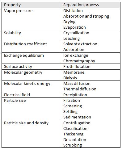
Essentially all chemical processes require the presence of a separation stage. Most chemical plants comprise of a reactor surrounded by many separators. Separators have a countless number of jobs inside of a chemical plant. A separator can process raw materials prior to the reaction, remove incondensable gases, remove undesired side products, purify a product stream, recycle materials back into the process, and many other jobs that are essential to the process.
Chemical engineers must understand the science of separation and the variety of ways that separation can take place. There are many ways to perform a separation some of these including: distillation, absorption, stripping, and extraction. The science of separation revolves around the presence of two phases that are in contact and equilibrium [1].
Theory
Vapor-Liquid Equilibrium
Separation processes are based on the theory of vapor-liquid equilibrium. This theory states that streams leaving a stage in a separation process are in equilibrium with one another. The idea of equilibrium revolves around the idea that when there is vapor and liquid in contact with one another they are in constantly vaporizing and condensing. Different components in the mixture will condense and vaporize at different rates. There are three types of equilibrium conditions that can be subdivided into thermal, mechanical and chemical potential categories. These separate equilibrium states are given as:
Failed to parse (SVG with PNG fallback (MathML can be enabled via browser plugin): Invalid response ("Math extension cannot connect to Restbase.") from server "https://wikimedia.org/api/rest_v1/":): {\displaystyle p_{liquid} = p_{vapor}}
Failed to parse (SVG with PNG fallback (MathML can be enabled via browser plugin): Invalid response ("Math extension cannot connect to Restbase.") from server "https://wikimedia.org/api/rest_v1/":): {\displaystyle chemical potential_{liquid} = chemical potential_{vapor}}
Gas Separators
Distillation
History
Flash Distillation
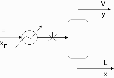
Flash Distillation is one of the simpler separation processes to be employed in a chemical plant. The main premise of flash distillation is that a portion of a liquid feed stream vaporizes in a flash chamber or a vapor feed condenses. Vapor-liquid equilibrium will cause the vapor phase and the liquid phase to have different compositions. The more volatile component of the mixture will compose of a larger portion of the vapor. This simple separation is easy to manufacture but does not result in large degrees of separation.
Flash distillation requires a feed stream that is pressurized and heated and then passed through a valve into a flash drum. The large pressure drop across the valve will result in a partial vaporization of the fluid. Vapor will be removed overhead from the flash drum while the remaining liquid will collect at the bottom of the drum and be removed. Most flash drums will contain an entrainment eliminator which is a screen that prevents liquid from being carried into the vapor effluent. Figure one shows a simple overview of the flash distillation process. As shown, there is a heater that flows into a let down valve where the two phase flow begins. Variables y and x are the mole fractions of the more volatile component in the vapor and liquid effluents respectively.
Column Distillation
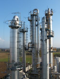
Distillation columns are the most widely used separation technique used in the chemical industry, accounting for approximately 90% of all separations [1]. Distillations in columns consist of multiple trays that each act at their own equilibrium conditions. Large columns are able to perform complete separations of binary mixtures as well as more complex multi-component mixtures.
Distillation Equipment
McCabe-Thiele Diagrams
Stages
Tray Type
Sieve
The simplest tray type is the sieve tray which is a sheet of metal with holes punched into it to allow vapor flow. Sieve trays can have different hole patterns and sizes that will affect the tray efficiency and flow rates.
Bubble Cap
Batch Distillation
Column Sizing
Tray spacing is largely dependent on the diameter of the column and will increase as the column grows larger. The typical stay spacing is between 0.5 m to 1.5 m [1].
Absorption
References
- Wankat, P.C. (2012). Separation Process Engineering. Upper Saddle River: Prentice-Hall.
- Towler, G.P. and Sinnot, R. (2012). Chemical Engineering Design: Principles, Practice and Economics of Plant and Process Design.Elsevier.
- Biegler, L.T., Grossmann, L.E., and Westerberg, A.W. (1997). Systematic Methods of Chemical Process Design. Upper Saddle River: Prentice-Hall.
- Peters, M.S. and Timmerhaus, K.D. (2003). Plant Design and Economics for Chemical Engineers, 5th Edition. New York: McGraw-Hill.
- Seider, W.D., Seader, J.D., and Lewin, D.R. (2004). Process Design Principles: Synthesis, Analysis, and Evaluation. New York: Wiley.
- Turton, R.T., Bailie, R.C., Whiting, W.B., and Shaewitz, J.A. (2003). Analysis, Synthesis, and Design of Chemical Processes Upper Saddle River: Prentice-Hall.


