Separator
Author: Matthew Hantzmon [2015]
Stewards: Jian Gong and Fengqi You
Introduction
The implementations of separation processes are of utmost importance in designing chemical plants. The product stream from a reactor is rarely close to the purity desired by the operator. There are either impurities from undesirable side reactions or unreacted species from the inlet stream. As a result, most chemical processes use an array of separation processes designed to purify the desired product and recycle remaining reactants back to the reactor feed. Aspen HYSYS V8.0 has an array of units that are able to simulate separation processes and estimate the composition of the product streams. By choosing parameters in the system in an consistent way, the operator can fully specify the system in a way that HYSYS can solve for the remaining parameters.
Types of Separation
There are many different types of separations utilized by engineers to purify their desired product. Though there are numerous uncommon types of separations that use niche techniques, most separations used in industry involve multi-phase separation. Multi-phase separation refers to the heterogeneous composition of the product and its tendency to split into multiple discrete mixtures.
Multi-Phase Separation
Multi-Phase separation plays a very important role in the purification of a desired product. It involves manipulating the conditions of a stream to cause the mixture to separate into distinct phases. Two common modes of this separation that can be modeled in HYSYS are flash separation and 3-phase separation. The common theme in these separations is that the mixture in the column is heterogeneous and one outlet stream will contain the desired product in a higher purity than it was at the inlet.
Flash Separation
Flash separation is a technique used to separate the gas and liquid species in a stream that is at vapor-liquid equilibrium (VLE). Either the species can be at VLE before entering the separator, or the separator may add or remove heat to bring the system to VLE (Towler and Sinnott, 2013). If there is no duty in the system, a fully specified feed attached to a separator will result in a fully specified system. If duty exists, either the duty must be specified or anther aspect of the product needs to be chosen for HYSYS to converge.
3-Phase Separation
Sometimes, especially in the presence of hydrocarbons and water, the liquid phase of the separation will not be homogeneous. This results from the fact that species within the liquid phase are not miscible with each other. The resulting separation will result in 3 unique streams, one in the vapor phase and two in the liquid phase. The vapor will still be in VLE with the liquid. As with the flash separation, a fully specified feed will result in a fully specified system if not duty is added. If there is duty in the separator, then another variable will need to be chosen.
HYSYS Simulation
To simulate a separation in HYSYS, first the simulation environment must be initialized. This includes first choosing all of the individual compounds that will exist in the overall system, and then choosing a fluid package that will accurately simulate all compounds in the range of expected temperatures and pressures. Once this is complete the simulation environment may be entered.
To begin building the process, first it is important to specify the feed stream that you are attempting to separate. These specifications include the composition, flow rate, temperature, and pressure of the stream. Once these parameters are entered, it is then necessary to connect the feed to the desired separator type and then run the simulation.
The following two case studies demonstrate how to accomplish a simple separation with a flash separator and a 3-phase separate. The components of the feed will be equal fractions water and ethanol for the flash separation and will be equal fractions water, ethanol, and benzene for the 3-phase separation. The flow rate will be 100 mol/hr in both systems and the NRTL fluid package will be utilized. The feed will be at 1atm pressure and have a .5 vapor fraction.
Flash Separator
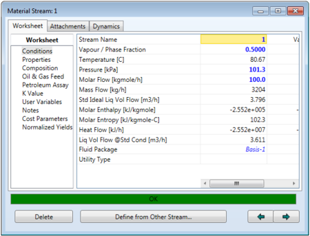
To simulate the flash separator, first the feed must be fully specified as shown below.
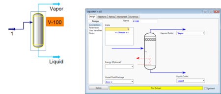
Then the feed can be connected to the separator, and outlet vapor and liquid streams can also be added. If the separator is left without a duty, then HYSYS will be able to solve for the outlet steams based on the VLE composition of the feed.
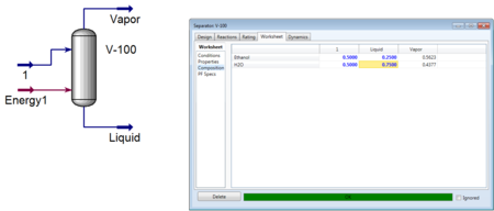
If a duty is added, the amount of heat added or taken away will determine the final separation. Either you can specify the duty or another parameter. If there are desired outlet compositions or flow rate from the system, it can be useful to specify one of those characteristics. After being specified, HYSYS will converge to a solution and the compositions of the outlet streams can be seen in the workbook.
In figure 3, the composition of the liquid stream was specified and HYSYS was able to calculate the vapor composition as well as other flow and energy parameters.
3-Phase Separator
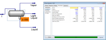
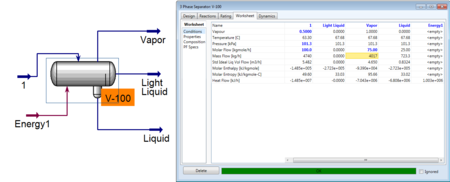
To simulate a useful 3-phase separator, a feed is needed that will separate into two liquid phases. The addition of benzene to the water ethanol system adds the desired element of immiscible liquid phases. The feed can be then specified as before and connected to the 3-Phase Separator. Vapor, light liquid, and heavy liquid product streams are added. As with the flash separator, the 3-phase separator is fully specified once the feed is specified.
However the addition of a duty allows the user to specify one aspect of the product streams. Usually it is useful to specify concentrations of one component in a product stream or possibly the flow rate of one of those streams.
As seen above, the user specified the vapor flow rate and HYSYS was able to converge and solve for the remaining unknowns in the system.
Conclusion
The process of simulating separation in HYSYS is fairly straightforward once the user has a fully specified feed. The feed specifications come from the description of the problem that the user is attempting to solve. Without added duty, the full specification of the feed is all the information that HYSYS needs to simulate the separation. Within the feed stream, two phases exist, and the composition and flow rate of each phase will determine the composition and flow rate of the two phases leaving the separator. The addition of duty complicates the problem slightly more, though it also gives the user more flexibility as they are able to specify one aspect of the product streams and customize their separation.
The choice between using a normal flash separator and a 3-phase separator depends on the species in the feed stream. If there are only two phases, the flash separator is sufficient, thought the exact same separation can be simulated with a 3-phase separator. In that case, the light liquid flow rate would be 0. However, if there are 3 phases in the feed stream it is necessary to simulate with a 3-phase separator. The flash separator would not work as the liquid stream would still contain two distinct phases.
References
- G.P. Towler, R. Sinnott, Chemical Engineering Design: Principles, Practice and Economics of Plant and Process Design, Elsevier, 2013.
- R.H. Perry, D. W. Green, Eds., Perry’s Chemical Engineers’ Handbook, 6th Ed., McGrawHill: New York, 1984.
- Ullmann’s Encyclopedia of Industrial Chemistry, 5th Ed., VCH: Deerfield Beach, 1988.
