Heat Transfer Equipment: Difference between revisions
No edit summary |
No edit summary |
||
| Line 33: | Line 33: | ||
<math>\Delta T _m</math> = log mean temperature difference or the temperature driving force, (temperature) |
<math>\Delta T _m</math> = log mean temperature difference or the temperature driving force, (temperature) |
||
<math>\Delta T _m</math> is the driving force for a pure countercurrent contact pattern in a tubular system. the correction factor <math>F</math> is used because most heat exchangers do not implement true countercurrent contact. Design equations for heat exchangers will use generally use some form of this equation with the appropriate modifications to account for different configurations and approximations. |
<math>\Delta T _m</math> is the driving force for a pure countercurrent contact pattern in a tubular system. the correction factor <math>F</math> is used because most heat exchangers do not implement true countercurrent contact. Design equations for heat exchangers will use generally use some form of this equation with the appropriate modifications to account for different configurations and approximations.<ref name="1'>{{12}} |
||
=Heat Exchangers= |
=Heat Exchangers= |
||
| Line 104: | Line 103: | ||
===Gas-to-Gas=== |
===Gas-to-Gas=== |
||
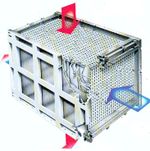
Gas-to-gas heat exchangers are primarily used to recover energy from combustion gases to preheat furnace air. The plain tube gas-to-gas heat exchanger is a simple countercurrent exchange through a tube bank, either in a single-pass (cross-flow) or multipass configuration. |
Gas-to-gas heat exchangers are primarily used to recover energy from combustion gases to preheat furnace air. The plain tube gas-to-gas heat exchanger is a simple countercurrent exchange through a tube bank, either in a single-pass (cross-flow) or multipass configuration<ref>Peters, M.P., Plant Design and Economics for Chemical Engineers 5th Ed., McGraw-Hill: New York, 2003.</ref> |
||
[[File:Gas-to-Gas Heat Exchanger.jpg|right|150px]] |
[[File:Gas-to-Gas Heat Exchanger.jpg|right|150px]] |
||
| Line 166: | Line 165: | ||
=References= |
=References= |
||
{{Reflist|1}} |
|||
<ref name = "1">Towler |
|||
<references> |
|||
</references> |
|||
Revision as of 04:46, 16 January 2014
Title: Heat Transfer Equipment
Author: David Chen
Steward: Fengqi You
Date Presented: January 13, 2014 /Date Revised: January 14, 2014
Basic Concept
There are three mechanisms of heat transfer: conduction, convection, and radiation. In most heat exchangers, convection will be the dominant mechanism. Conduction and radiation will generally be negligible in large heat exchangers, but radiation will be important in fired heaters.
Heat transfer across a surface by convection is given by the equation:
Where: = heat transferred per unit time (energy/time)
= overall heat-transfer coefficient (energy/time-area-temperature)
= area (area)
= correction factor (unitless)
= log mean temperature difference or the temperature driving force, (temperature)
is the driving force for a pure countercurrent contact pattern in a tubular system. the correction factor is used because most heat exchangers do not implement true countercurrent contact. Design equations for heat exchangers will use generally use some form of this equation with the appropriate modifications to account for different configurations and approximations.Cite error: Closing </ref> missing for <ref> tag
Boiling and Condensing Heat Transfer
Heat transfer involving boiling liquids or condensing vapor is different from heat transfer involving constant fluid phases. Heat transfer operations that involve phase changes are typically carried out in separate units in order to account for the different physical properties of the phases.
Boiling Heat Transfer
Boilers transfer heat to boil liquids.
Boiling Heat Transfer Coefficient
Boiling liquids have different heat transfer regimes. I: Heat transfer with natural convection II: Heat transfer with bubbling agitation III: Heat transfer with nucleate boiling with unstable film IV: Heat transfer with stable film boiling V: Radiant Heat Transfer
The heat transfer coefficient of a boiling liquid begins to decrease with the onset of film boiling. One method of improving the overall heat transfer coefficient is to use high-flux tubing, which utilizes a porous coating inside of tubes. It can improve boiling performance up to 10 times over a bare tube, and overall performance 2 to 5 times over a bare tube.
Kettle Reboilers
Kettle reboilers are often used as a steam generator. Pool boiling is used in kettle reboilers. In pool boiling, agitation occurs through bubbling and natural convection. The vapor-liquid separator is built-in and allows for blowdown. The weir helps to maintain the liquid level above the tube bundle. It also helps to prevent the entering bubble point liquid (distillation bottoms) from mixing with the residual reboiled liquid (exiting from the bottom). Kettle reboilers are more expensive than horizontal thermosiphons fabricated for a comparable duty.
Thermosiphon Reboilers
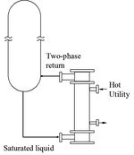
Thermosiphon reboilers use flow boiling. In flow boiling, agitation occurs through bubbling and forced convection at high velocities. They can be located at a height below the column sump. This allows the static head of the sump to force the column bottoms into the reboiler, which is designed for about 25 to 33% vaporization per pass. Thermosiphon reboilers can be vertical (tube-side) or horizontal (shell-side flow). Horizontal thermosiphon reboilers tend to be cheaper than vertical thermosiphons, but vertical thermosiphons are better at handling dirty fluids.
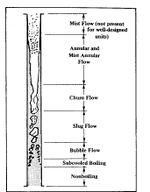
Flow is critical in a thermosiphon reboiler, and the different flow regimes will impact operation. The different flow regimes are caused by the increasing vapor/liquid ratio as the fluid passes through the thermosiphon.
Flow regimes in order of increasing vapor/liquid ratio: nonboiling < subcooled boiling < bubble flow < slug flow < churn flow < annular and mist flow < mist flow
Slug flow is unavoidable, but should be minimized. It causes noise and vibration in the thermosiphon. Annular and mist flow are also undesirable. Annular flow can be avoided by designing for less than 33% vaporization, and mist flow can be altogether avoided in well-designed reboilers.
Stab-in Reboilers
Stab-in reboilers are essentially the heat exchange tube bundle fitted inside a sump. In this case, the sump behaves in a similar capacity to a kettle reboiler, and mechanism of pooling is again pool boiling. It is important that there is enough space in the sump for good level control and to contain the entire tube bundle.
Condensing Heat Transfer
Condensing heat transfer is important because many heat transfer applications will condense the steam used as the hot stream, and often gaseous products are needed in liquid form. There are two types of condenser: total condensers and partial condensers. Both total and partial condensers need to account for the accumulation of noncondensable vapor. This can be done by venting through the top of the exchanger. The tube bundle arrangement affects overall heat transfer as well. Falling condensate from higher to lower tubes increases local turbulence and thus the heat transfer coefficient. However, condensate that collects on a tube and has yet to drain prevents the cooled heat transfer surface from contacting the vapor.
Total Condenser
In a total condenser, all the vapor that enters is condensed as a film on the heat transfer surface. The heat transfer coefficient is determined only by the thermal resistances.
Partial Condenser
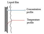
In a partial condenser, not all of the vapor that enters is condensed. This allows for vapor-liquid separation. However, there will be a a vapor film with a higher concentration of high-boiling products. The heat transfer coefficient is not determined solely by the thermal resistance, but also in part by the mass transfer resistance as well. The condensable component of vapor will have to diffuse through the noncondensable component. The resistance to diffusion leads to a much lower overall heat transfer coefficient. Additionally, it complicates the calculation of heat transfer.
Heaters and Coolers
References
<ref name = "1">Towler


