Reactors: Difference between revisions
| Line 80: | Line 80: | ||
In most cases the main process reaction rate equations and rate constants cannot be predicted from first principles and must be approximated [1]. This is due to the following: |
In most cases the main process reaction rate equations and rate constants cannot be predicted from first principles and must be approximated [1]. This is due to the following: |
||
* Use of heterogeneous catalysis or enzymes which lead to |
* Use of heterogeneous catalysis or enzymes which lead to Langmuir-Hinshelwood-Hougen-Watson or Michaelis-Menten kinetics |
||
* Mass transfer between vapor and liquid or two liquid phases |
* Mass transfer between vapor and liquid or two liquid phases |
||
* Multistep mechanisms whose rate expressions do not follow overall reaction stoichiometry |
* Multistep mechanisms whose rate expressions do not follow overall reaction stoichiometry |
||
Revision as of 19:40, 9 February 2014
Title: Reactors
Author: Sean Cabaniss, David Park, Maxim Slivinsky and Julianne Wagoner
Steward: Fengqi You
Date Presented: February 4, 2014
Introduction
Ideal Reactors
Batch Reactors
Plug Flow Reactor (PFR)
A PFR with tubular geometry has perfect radial mixing but no axial mixing. All materials hav the same residence time, τ, and experience the same temperature and concentration profiles along the reactor. Equation for PFR is given by:
where M = molar flow rate, dV is the incremental volume, and is the rate of reaction per unit volume.
This equation can be integrated along the length of the reactor to yield relationships between reactor resident time and concentration or conversion.
Continuously Stirred Tank Reactor (CSTR)
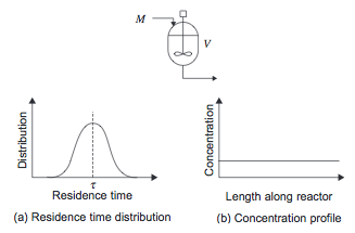
The stirred tank reactor models a large scale conventional laboratory flask and can be considered to be the basic chemical reactor. In a CSTR, shown in Figure 1, there is no spatial variation- the entire vessel contents are at the same temperature, pressure, and concentration. Therefore the fluid leaving the reactor is at the same temperature and concentration as the fluid inside the reactor.
The material balance across the CSTR is given by:
Some of the material the enters the reactor can leave immediately, while some leaves much later, so there is a broad distribution in residence time as shown in Figure 1.
Figure 1. Continuously Stirred Tank Reactor [1]
More information on stirred tanks can be found in the Mixing section.
General Reactor Design
The design of the reactor should not be carried out separately from the overall process design due to the significant impact on capital and operating costs on other parts of the process[1].
Collect Required Data
Out of all process equipment, reactor design requires the most process input data: reaction enthalpies, phase-equilibrium constants, heat and mass transfer coefficients, as well as reaction rate constants. All of the aforementioned parameters can be estimated using simulation models or literature correlations except for reaction rate constant constants, which need to be determined experimentally [1].
Enthalpy of Reaction
The heat given out in a chemical reaction is based on the enthalpies of the component chemical reactions, which are given for standard temperature and pressure (1 atm, 25 C). Values for standard heats of reaction can be found tabulated in literature, or can be calculated from heats of formation or combustion. Care must be taken to quote the basis for the heat of reaction and the states of reactants and products.
The following equation is used to convert enthalpies from standard conditions to the process conditions:
If the effect from pressure is not significant and only Temperature needs to be accounted for, the following equation should be used:
Equilibrium Constant and Gibbs Free Energy
Where is the change in Gibbs free energy from the reaction at temperature , is the ideal gas constant, and is the reaction equilibrium constant, given by:
where is the activity of component i, is the stoichiometric coefficient of component , and is the total number of components.
Equilibrium constants can be found in the literature and are useful for evaluating the rates of forward and reverse reactions. Care must be taken to the experimental design used for the literature equilibrium constants to make sure they are consistent with the conditions of the actual process reactor. For more complicated reactions consisting of several sequential or simultaneous reactions, the equilibrium is found by minimizing the Gibbs free energy [1]. Commercial process simulation programs use the Gibbs reactor model in this way.
Reaction Mechanisms, Rate Equations, and Rate Constants
In most cases the main process reaction rate equations and rate constants cannot be predicted from first principles and must be approximated [1]. This is due to the following:
- Use of heterogeneous catalysis or enzymes which lead to Langmuir-Hinshelwood-Hougen-Watson or Michaelis-Menten kinetics
- Mass transfer between vapor and liquid or two liquid phases
- Multistep mechanisms whose rate expressions do not follow overall reaction stoichiometry
- Competing side reactions
As a result the main process reaction is usually approximated as first- or second-order over a narrow range of process conditions (temperature, pressure, species concentrations) to estimate the residence time required for a target conversion. Rate equations are always a fit for experimental data and should thus be used for interpolation within the data. It is important to collect more data when extrapolating, especially for exothermic reactions which have the potential for runaway [1].
Heat and Mass Transfer Properties
The design of internal heating or cooling devices can be found in Heat transfer equipment: Heat exchangers, boilers, condensers, heaters and coolers. Correlations for tube-side heat-transfer coefficients for catalyst-packed tubes of a heat exchanger are given below:
For heating:
and for cooling:
where is the tube-side heat transfer coefficient for a packed tube, is the tube diameter, is the fluid thermal conductivity, is the fluid density, is the superficial velocity, is the effective particle diameter, and is the fluid viscosity.
Diffusion coefficients are necessary when mass transfer can limit the rate of reaction, such as in catalytic reactions or reactions involving mass transfer processes such as gas absorption, distillation, and liquid-liquid extraction.
The diffusivity for gases can be estimated by the following correlation (Fuller, Schettler, Giddings):
where is the diffusivity, is temperature, are the molecular masses of components and , is the total pressure, and are the summation of special diffusion volume coefficients for components and , given in the table below:
(volume coefficient table from towler)
Select Reaction Conditions
Chemical or Biochemical Reaction
Catalyst
Temperature
Pressure
Reaction Phase
Solvent
Concentrations
Determine Materials of Construction
Determine Rate-Limiting Step and Critical Sizing Parameters
The key parameters that determine the extent of reaction must be identified by carrying out an experiment plan with a broad range of conditions. In general, the rate of reaction is usually limited by the following fundamental processes. The first three have been discussed in previous sections. Mixing will be developed in more detail in its own section.
- Intrinsic kinetics: There will usually be one slowest step that governs the overall rate.
- Mass-transfer rate: In multiphase reactions and processes that use porous heterogeneous catalysis, mass transfer can be particularly important. Often, careful experimentation will be needed to separate the effects of mass transfer and the rate of reaction to determine which is the rate-limiting step.
- Heat-transfer rate: The rate of heat addition can become the governing parameter for endothermic reactions. Heat-transfer devices such as heat exchangers or fired heaters may need to be used.
- Mixing: The time taken to mix the reagents can be the limiting step for very fast reactions.
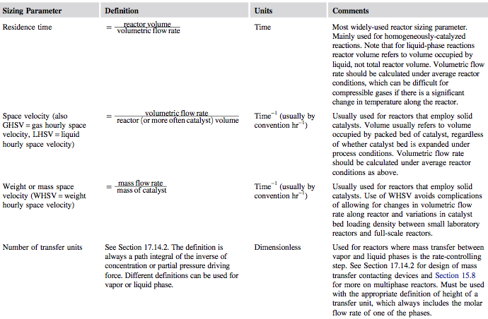
Once rate data have been collected, the designer can fit a suitable model of reaction kinetics. Next, a critical sizing parameter can be specified for the reactor. This will usually be one of the parameters given in Figure 1.
Figure 1. Reactor Sizing Parameters [1]
Preliminary Sizing, Layout, and Costing of Reactor
Estimate the Performance
Optimize the Design
Mixing in Industrial Reactors
Mixing plays an important role in many processing stages, including reactor performance. It is critical to select the appropriate method of mixing in order to ensure the process produces the desired process yields, product purity, and cost effectiveness.
Correlations such as the Reynolds number can be used to determine the extent of mixing and correlate power consumption and heat transfer to the reactor shell [2]. In some cases, simple correlations may not be adequate:
- If dead zones cannot be tolerated for reasons of product purity, safety, etc.
- If reactor internals are complex
- If reaction selectivity is very sensitive to mixing
In these cases, it is usually necessary to carry out a more sophisticated analysis of mixing:
- Use computational fluid dynamics to model the reactor
- Use physical modeling (“cold flow”) experiments
- Use tomography methods to look at performance of real reactor
Gas Mixing
Gases mix easily because of their low viscosities. The mixing given by turbulent flow in a length of pipe is usually sufficient for most purposes [1]. Orifices, vanes, and baffles can be used to increase turbulence.
Liquid Mixing
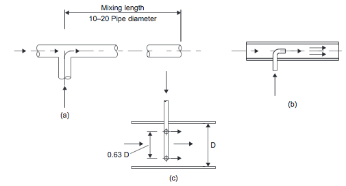
- Inline Mixing Inline mixers can be used for the continuous mixing of low-viscosity fluids. One inexpensive method involves the use of static devices that promote turbulent mixing in pipelines. Some typical designs are shown in Figures 2(a), (b), and (c).
- Figure 2. Inline mixers: (a) tee; (b) injection; (c) annular [1]
- When mixing low viscosity fluids (<50 mNs/m2) with similar densities and flow rates, a simple mixing tee, Figure 2(a), followed by a length of pipe equal to 10 to 20 pipe diameters, is suitable [1].
- When one flow is much lower than the other, an injection mixer, Figure 2(b&c), should be used. A satisfactory blend will be achieved in about 80 pipe diameters [1]. Baffles or other flow restrictions can be used to reduce the mixing length required. These mixers work by introducing one fluid into the flowing stream of the other through a concentric pipe or an annular array of jets [1].
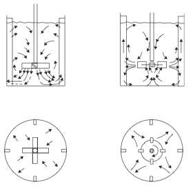
- Stirred Tanks Stirred tanks were discussed in the Ideal Reactors section. Mixing is conducted by an impeller mounted on a shaft driven by a motor. The reactor usually contains baffles or other internals to induce turbulence and prevent the contents from swirling and creating a vortex. Typically, baffles are 1/10 of diameter and located 1/20 of diameter from wall [2]. A typical arrangement of agitator and baffles in a stirred tank, and the flow pattern generated, is shown in Figure 3. Mixing occurs through the bulk flow of the liquid and by the motion of the turbulent eddies created by the agitator. Bulk flow is the predominant mixing mechanism required for the blending of miscible liquids and for solids suspension. Turbulent mixing is important in operations involving mass and heat transfer, which can be considered as shear-controlled processes [1].
- Figure 3. Agitator arrangements and flow patterns [1]
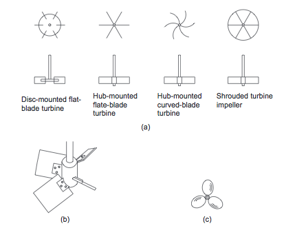
- At high Reynolds numbers (low viscosity), one of the three basic types of impeller shown in Figure 4 should be used. For processes controlled by turbulent mixing, the flat-bladed (Rushton) turbines are appropriate. For bulk mixing, the propeller and pitched-bladed turbines are appropriate [1].
- Figure 4. Basic impeller types [1]
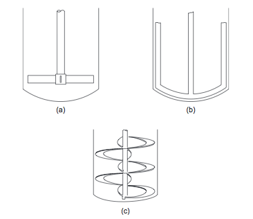
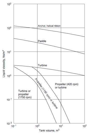
- For more viscous fluids, paddle, anchor, and helical ribbon agitators (Figures 5(a), (b), and (c)), are used [1]. The selection chart given in Figure 6 can be used to make a preliminary selection of the agitator type, based on the liquid viscosity and tank volume [1].
- Figure 5. Low-speed agitators [1]
- Figure 6. Agitator selection guide [1]
Gas-Liquid Mixing
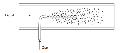
Gases can be mixed into liquids using the inline mixing or stirred tank methods discussed previously. A special type of gas injector, called a sparger (shown in Figure 7) can also be used. This is a long injection tube with multiple holes drilled in it.
Figure 7. Gas sparger [1]
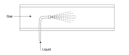
A small flow of liquid can be dispersed into a gas stream using a spray nozzle (Figure 8).
Figure 8. Liquid injection into gas [1]
Solid-Liquid Mixing
Solids are usually added to a liquid in a stirred tank at atmospheric pressure. In order to allow more accurate control of dissolved solid concentration, mixing of solids and liquids is often carried out as a batch operation [1].
Heating and Cooling of Reacting Systems
Types of Reactors
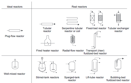
Most reactors used in industry approximate the ideal batch reactor, PFR, or CSTR. In fact, real reactors can be modeled as networks or combinations of multiple plug-flow and stirred-tank reactors [1]. Examples of real reactors that approximate the flow pattern of ideal reactors are shown in Figure 10. These reactors will be discussed in more detail in the following sections.
Figure 10. Ideal reactors and some real reactors that approximate the same flow pattern [1]
Vapor-Liquid Reactors
Vapor-liquid reactions are important in many chemical processes. For example, oxygenation and hydrogenation reactions are usually carried out with the organic component in the liquid phase [1]. A summary of common goals for vapor-liquid reactors and the reactors used to achieve those goals is shown in Table 1.
| Goal | Types of Vapor-Liquid Reactors | Examples |
|---|---|---|
| Maintain low concentration of gas component in liquid |
|
|
| Contact gas and liquid over catalyst |
|
|
| React a component out of the gas phase to high conversion |
|
|
Table 1. Summary of Vapor-Liquid Reactors [2]
If the residence time requirements are short enough, vapor-liquid contacting columns are preferred because of the high area for mass transfer. Trayed or packed columns can be used to contact vapor and liquid for reaction. The column packing may be catalytically active or could be inert packing [2]. Please see the separation processes section of this website for more information on the types of processes used for the third goal listed.
Stirred tanks or tubular reactors are used when long residence time is needed for the liquid phase [1]. These types of reactors and more will be discussed in the catalytic processes section of this page.
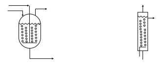
The reactors listed under the first goal in the table are unique to vapor-liquid processes. The basic concept of a sparger was discussed in the mixing section. Sparged reactors are shown in Figure 11.
Figure 11. Sparged stirred tank and tubular reactors [2]
The gas is bubbled up through the liquid in a sparged reactor. For smaller bubbles, a porous pipe diffuser can be used instead [2]. The designer must allow some disengaging space at the top of the reactor, or entrainment will be excessive. If the gas flow rate is large then the gas flow can be used as the primary means of agitation. Perry's Handbook suggests the following air rates (ft3/ft2min) for agitating an open tank full of water at 1 atm:
| Degree of agitation | Liquid depth 9 ft | Liquid depth 3 ft |
|---|---|---|
| Moderate | 0.65 | 1.3 |
| Complete | 1.3 | 2.6 |
| Violent | 3.1 | 6.2 |
Table 2. Summary of suggested flow rates for gas flow as agitation [2]
Catalytic Processes
A catalyst increases the rate of a chemical reaction without itself becoming permanently changed by the reaction. Catalysts allow reactions to be run in smaller reactors and operated at lower temperatures and improve selectivity. Therefore, catalysts will almost always lead to a more economically attractive process than a noncatalytic route. [1] Catalysts are normally selected based on performance rather than price since increases catalysts selectivity will almost always quickly pay back any price premium expected by the manufacturer. It is important to test the catalysts under conditions that are representative of process conditions [1].
Catalyst activity often deteriorates over time [2]. Common causes of deactivation include:
- Poisoning by components in feed (e.g. base destroys acid catalyst)
- Blockage of pores or active sites by byproducts such as coke
- Thermal or hydrothermal modification of catalyst structure
Slow activity loss can be compensated by:
- Putting in more catalyst (lower space velocity)
- Slowly raising reactor temperature
Rapid activity loss may require moving the catalyst to a continuous regeneration zone [2].
Catalytic reactions can be either homogenous (catalyst is in the same phase as the reagents) or heterogeneous (catalyst is not in the same phase as the reagents).
Homogeneous Catalysis
- Homogeneous catalysis can be conducted in the basic batch reactors, PFRs, or CSTRs that have already been discussed. However, when the catalyst is in the same phase as the reagent, recovering this catalyst after the reaction can be difficult and expensive, particularly if the catalyst is sensitive to high temperatures [2]. Providing adequate interfacial area is also a challenge of homogeneous catalysis. A reaction often only occurs at the interface or in the boundary layer between the catalyst and the reagents. Increased mixing can increase the rate and selectivity of the reaction, but this can require detailed and expensive mixing equipment [2]. For these reasons, reactions requiring homogenous catalysts are not usually used unless an easy separation can be found to recover the catalyst.
Heterogeneous Catalysis
- Catalyst recovery in processes involving heterogeneous catalysis is much easier. However, the rate of reaction is limited by the available inter-phase surface area and the mass transfer of reagents and products to and from the interface [2]. Therefore, reactors for these processes are design to reduce these limitations.
- Fixed Bed Reactors
- In a fixed-bed reactor, the reagent flows over a stationary bed of packed catalyst [1]. This is the most common type of reactor used for heterogeneous catalysis as long as the catalyst does not require continuous regeneration and the reaction mixture does not require high agitation [2]. The amount of catalyst necessary can be found using the following equations:
- The ratio of the bed height (L) to the diameter (D) determines the distribution of reagents and the pressure drop across the bed. An increased L/D ratio creates a more even distribution and less change of localized deactivation or "hot spots." However, increasing the L/D ratio increases the pressure drop, requiring higher compression and pumping costs [2]. The Ergun equation can be used to calculate the pressure drop in packed beds.
- Where V is the superficial velocity (volume flowrate divided by cross-sectional area), μ is the viscosity, Dp is the particle diameter and ε is the porosity of the packed bed [2]. Given these trade-offs, it may make sense to split the catalyst over several beds [2].
- Radial Flow Reactors
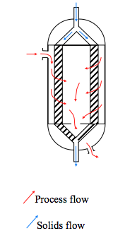
- When there is very little pressure drop available, the L/D ratio must be much less that one [2]. A common solution to this is to use a radial flow reactor with the catalyst contained in an annulus between vertical perforated or slotted screens. The fluid flows radially through the bed and the direction of flow can be either inwards or outwards [1]. An example of a radial flow reactor is shown in Figure 12.
- Figure 12. Radial flow reactor [2]
- Moving Bed Reactors
- A moving bed reactor is similar to a radial flow reactor, but the catalyst is moved through the annular space [2].
- Fluidized Bed Reactors
- If the fluid flow is up through the catalyst bed then the bed can become fluidized if the pressure drop is high enough to support the weight of the catalyst. Fluidized beds usually have a lower pressure drop than down flow at high flow rates [2]. In addition, fluidizing the catalyst eases the transition from one reaction zone to another.
- The catalyst bed is fluidized using a distributor to inject fluidization fluid, which is not necessarily the feed. Fluidization occurs when the bed pressure drop balances the weight of the particles, or
- Where ∆P is the pressure drop, ρp and ρg are the densities of the particle and gas respectively, εm is the porosity at minimum fluidization, and L is the height of the bed [2]. Fluidization can only be used with relatively small sized particles (<300 micrometers with gases). The solid material must be strong enough to withstand attrition in the fluidized bed and cheap enough to allow for make-up to replace attrition losses [1]. A fluidized-bed reactors must also make allowance for separating the fluid-phase product from entrained solids so that solids are not carried out of the reactor [1].
- Trickle Bed Reactors
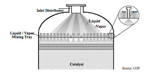
- Trickle bed reactors are used when all three phases are involved in the reaction. They must ensure good distribution of both the vapor and the liquid, without channeling of either phase [2]. In a trickle bed reactor, the liquid flows down over the surface of a stationary bed of solids. The gas phase usually also flows downwards with the liquid, but countercurrent flow is feasible as long as flooding conditions are avoided [1]. This requires a more sophisticated distributor like those used for packed distillation columns [2]. An example of a trickle bed reactor is shown in Figure 13.
- Figure 13. Example of trickle bed reactor [2]
- Slurry Reactors
- Liquid is mixed up in the liquid in slurry phase reactions. Slurry reactors are prone to attrition of the solids, caused by pumping or agitation of the liquid [1]. Slurry-phase operation is usually not preferred for processes that use heterogeneous catalysts because the catalyst tends to become eroded and can be difficult to recover from the liquid [1].
Bioreactors
Enzyme Catalysis
Cell Growth
Types of Bioreactors
- Stirred Tank Fermenter
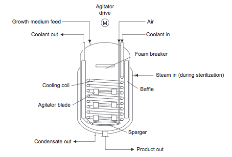
- Figure 14. Fermentation reactor [1]
- Shaftless Bioreactors
Safety Considerations in Reactor Design
Reactors require much attention to safety details in the design process due to the hazards they impose. They are often the highest temperature point in the process, heat of reaction may be released, and residence times can be long leading to a large inventory of chemicals. Guidelines exist for inherently safer design principles which seek to remove or reduce process hazards, limiting the impact of unforeseen events. These design methods should be applied throughout the design process as part of good engineering practice; they cannot be retroactively added by a process safety specialist. Some examples are given in the table below:
(table 15.16 in Towler)
Exothermic reactions require special consideration due to their potential to runaway (temperature rises from heat of reaction being released, increasing reaction rate, releasing more heat, and so on). The reactor must be designed such that temperature can be precisely controlled and the reaction shut down if temperature control is lost. The use of solvents or inert species also allows for temperature control by adjusting heat capacity flow rate relative to rate of heat release from the reaction. An additional safety feature would allow the reactor to be flooded with cold solvent or diluent.
If there is a cooling system it should be designed to return the process to desired temperature if the maximum temperature is reached.
Venting and relief of reactors is complicated by the potential to keep reacting if containment is lost or material is discharged into the pressure relief system. The relief system should be designed according to guidelines outlined in the Design Institute for Emergency Relief Systems (DIERS) methodology. The reactor design team must understand the reaction mechanism and kinetics, including the role of any compounds which may accelerate the reaction. Details may be found on the AIChE website, here.
Capital Cost of Reactors
Reactors are classified as pressure vessels, and as such the pressure vessel design methods can be used to estimate wall thickness and thus determine capital cost. Additional costs come from reactor internals or other equipment. Jacketed stirred-tank reactors require more in depth analysis than that provided by pressure vessel design. The wall of the reaction vessel may be in compression due to the jacket. For preliminary cost estimating a correlation for jacketed stirred tank reactors operating at pressures below 20 bar can be used:
where is the purchased equipment cost on a U.S. Gulf Coast Basis, are cost constants, is the size parameter, and is the exponent for that type of equipment. Values for are given in the table below:
(Table 7.2 Towler)
Conclusions
References
- Towler, G.P. and Sinnot, R. (2012). Chemical Engineering Design: Principles, Practice and Economics of Plant and Process Design. Elsevier.
- Towler, G.P. (2012). Chemical Engineering Design, PowerPoint presentation.




![{\displaystyle D_{v}={\frac {1.013\times 10^{-7}T^{1.75}{\left({\frac {1}{M_{a}}}+{\frac {1}{M_{b}}}\right)}^{1/2}}{P{\left[{\left(\sum _{a}v_{i}\right)}^{1/3}+{\left(\sum _{b}v_{i}\right)}^{1/3}\right]}^{2}}}}](https://wikimedia.org/api/rest_v1/media/math/render/svg/c9be45b7d1a85b5a6d4d71a69116e3e0bd7dbbc1)


