Uncategorized files
Jump to navigation
Jump to search
Showing below up to 250 results in range #251 to #500.
 Eqn2.png 156 × 20; 999 bytes
 Eqn3.png 70 × 29; 814 bytes
 Eqn4.png 338 × 33; 3 KB
 Eqn5.png 103 × 29; 907 bytes
 Equation.PNG 911 × 379; 20 KB
 EquipCosts.PNG 902 × 472; 67 KB
 EquipSummary.PNG 580 × 370; 22 KB
 Equipment Costs.JPG 816 × 748; 146 KB
 Equipment cost.JPG 319 × 491; 51 KB
 Equipment sizes.png 432 × 624; 76 KB
 Ergun.png 300 × 59; 12 KB
 Ethanol-ethylenepfd.png 1,215 × 660; 91 KB
 Ethanol.JPG 591 × 366; 35 KB
 Example.jpg 831 × 425; 71 KB
 Example10.png 659 × 358; 360 KB
 Example11.jpg 341 × 329; 15 KB
 Example11.png 589 × 401; 340 KB
 Example2.jpg 1,071 × 375; 50 KB
 Example3.jpg 241 × 241; 8 KB
 Example4.jpg 240 × 245; 8 KB
 Example5.jpg 239 × 244; 9 KB
 Example6.jpg 240 × 245; 8 KB
 Example7.jpg 241 × 245; 7 KB
 Example8.png 654 × 821; 197 KB
 Example9.png 150 × 157; 50 KB
 ExampleChemicals.jpg 900 × 511; 177 KB
 F1.PNG 420 × 285; 29 KB
 F2.PNG 634 × 349; 29 KB
 F3.PNG 466 × 192; 16 KB
 F4.PNG 633 × 245; 29 KB
 FBRsteps.png 489 × 525; 40 KB
 FailureCost.jpg 470 × 623; 70 KB
 Feed.png 1,005 × 504; 29 KB
 FeedConditions.PNG 583 × 538; 30 KB
 Feed sterilization.jpg 311 × 141; 8 KB
 FeedbackControlLoop.png 800 × 279; 10 KB
 Feedback Control1.png 1,310 × 844; 27 KB
 Feedback Control2.png 1,340 × 843; 27 KB
 Feedforward Control.png 1,270 × 866; 30 KB
 Feedstock.PNG 696 × 299; 18 KB
 Fermentation.png 474 × 321; 39 KB
 Fig1-1.png 1,192 × 621; 427 KB
 Fig1.jpg 1,204 × 454; 70 KB
 Fig1128.jpg 337 × 316; 25 KB
 Fig1129.jpg 390 × 299; 45 KB
 Fig1130.jpg 268 × 353; 27 KB
 Fig1131.jpg 432 × 528; 92 KB
 Fig1132.jpg 432 × 338; 23 KB
 Fig1133.jpg 346 × 412; 19 KB
 Fig1135.jpg 404 × 382; 20 KB
 Fig1136.jpg 432 × 583; 42 KB
 Fig2-1.png 1,403 × 481; 48 KB
 Fig2.jpg 1,204 × 474; 79 KB
 Fig4.PNG 925 × 462; 73 KB
 Fig5-1.png 431 × 282; 154 KB
 Fig5.PNG 905 × 582; 66 KB
 Fig7-1.png 236 × 400; 147 KB
 Figure2RHP.png 1,199 × 519; 24 KB
 Figure3RHP.PNG 489 × 359; 12 KB
 Figure4RHP.PNG 514 × 364; 19 KB
 FigureA1RHP.png 509 × 339; 242 KB
 FigureB1RHP.png 957 × 709; 255 KB
 FigureE1RHP.png 1,428 × 746; 130 KB
 FigureG1RHP.png 719 × 377; 25 KB
 FigureG2RHP.png 768 × 402; 28 KB
 FigureG3RHP.png 1,038 × 851; 43 KB
 FigureJ1RHP.PNG 582 × 772; 164 KB
 FigureM1RHP.PNG 683 × 811; 187 KB
 FigureM2RHP.PNG 692 × 704; 215 KB
 FigureM3RHP.PNG 533 × 338; 10 KB
 Figure 1.PNG 475 × 573; 44 KB
 Figure 1. Plant Location in Liberia, Costa Rica.JPG 773 × 621; 114 KB
 Figure 1.jpg 208 × 217; 13 KB
 Figure 1.png 642 × 342; 36 KB
 Figure 2.PNG 466 × 522; 38 KB
 Figure 2. Aspen Hysys Separation Model.JPG 1,255 × 479; 63 KB
 Figure 2.jpg 193 × 126; 9 KB
 Figure 3.PNG 468 × 396; 39 KB
 Figure 3. Process Control PFD.JPG 1,065 × 743; 66 KB
 Figure 3.jpg 195 × 152; 12 KB
 Figure 4.jpg 221 × 79; 8 KB
 Figure 4.png 603 × 269; 43 KB
 Final Hysys PictureG1.jpg 2,937 × 750; 413 KB
 Final Hysys PictureSmallG1.jpg 1,958 × 500; 232 KB
 Find Compound 3.png 545 × 572; 157 KB
 Firedheater.png 696 × 441; 101 KB
 Flash.gif 396 × 271; 2 KB
 Floodingplot.jpg 337 × 262; 39 KB
 Flow compressor.jpg 2,788 × 2,308; 1.19 MB
 Fluid Eqn.png 182 × 31; 9 KB
 Fluidized Bed Pic.png 122 × 336; 23 KB
 Fluidized Bed Pic1.png 122 × 336; 23 KB
 Fluidized bed.PNG 571 × 351; 51 KB
 Fluidized bed with a cyclone.png 398 × 270; 28 KB
 Fluidpkg.PNG 630 × 664; 31 KB
 Fluidz.JPG 1,343 × 489; 63 KB
 Fouling.jpg 259 × 194; 15 KB
 Full Composite CurveG1.JPG 1,231 × 578; 56 KB
 GWP.PNG 543 × 444; 37 KB
 Galvanic Series.gif 813 × 979; 162 KB
 Galvanic Series2.png 393 × 474; 93 KB
 Gams.PNG 441 × 178; 13 KB
 Gams problem.JPG 337 × 236; 26 KB
 Gams problem.png 437 × 309; 17 KB
 Gams solution.JPG 299 × 129; 19 KB
 Gas-to-Gas Heat Exchanger.jpg 366 × 368; 51 KB
 Gas Sparger.PNG 406 × 175; 19 KB
 Gas pollutants.png 691 × 654; 158 KB
 GaseousPollutants.png 970 × 994; 216 KB
 Gasket.jpg 254 × 192; 10 KB
 Gasketed-Plate Heat Exchanger.gif 264 × 199; 26 KB
 Gasmixer.jpg 305 × 296; 16 KB
 GenericCSTR.png 674 × 484; 32 KB
 GibbsType.png 763 × 323; 23 KB
 Glycerol.png 609 × 421; 52 KB
 HENG1.JPG 1,600 × 701; 167 KB
 HSYYSfull.png 1,271 × 501; 54 KB
 HX2.jpg 1,746 × 516; 216 KB
 HYSYS1.png 624 × 246; 32 KB
 HYSYS2.png 624 × 348; 38 KB
 HYSYS B1.PNG 1,393 × 320; 19 KB
 HYSYS Simulation.JPG 1,001 × 431; 41 KB
 HYSYSamine.png 619 × 348; 19 KB
 Hazards 1.PNG 856 × 346; 32 KB
 Hazards 2.PNG 336 × 329; 34 KB
 Hazards 3.PNG 848 × 449; 92 KB
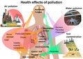 Health effects of pollution.png 624 × 443; 304 KB
 Heat Exchanger Network.jpg 558 × 530; 80 KB
 Heat exchanger 2.png 1,746 × 516; 81 KB
 Hen loop.jpg 509 × 146; 13 KB
- Error creating thumbnail: File with dimensions greater than 12.5 MPHigh Quality PFDG1.png 10,709 × 3,019; 486 KB
 High Quality PFDSmallG1.png 1,774 × 500; 104 KB
 High output 1.PNG 751 × 526; 47 KB
 HisTagPurification.PNG 981 × 412; 305 KB
 Hollow membrane.jpg 521 × 151; 14 KB
 Hydrocracking.png 230 × 337; 26 KB
 HydrogenNPV.png 624 × 369; 16 KB
 Hydrogenflowsheet.png 1,002 × 732; 73 KB
 Hysys.JPG 470 × 144; 17 KB
 Hysys.png 1,552 × 554; 49 KB
 Impeller Types.PNG 413 × 331; 33 KB
 Io example.JPG 462 × 180; 13 KB
 KZ SafetyLayers.PNG 602 × 537; 73 KB
 Kettle Reboiler.png 697 × 608; 18 KB
 Lamella Clarifier.png 425 × 296; 231 KB
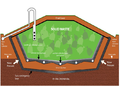 Landfill.png 672 × 480; 400 KB
 Layers of Plant Safety.png 1,332 × 1,040; 108 KB
 Lifecycle.PNG 333 × 256; 13 KB
 Lifecycle2.PNG 537 × 189; 15 KB
 LiquidLiquid.JPG 39 × 37; 8 KB
 Liquid Injection.PNG 426 × 183; 14 KB
 Liquidflow.jpg 164 × 225; 15 KB
 Low Speed Agitators.PNG 366 × 316; 22 KB
 Making a new spec.PNG 414 × 356; 39 KB
 MapABC.jpg 1,402 × 575; 131 KB
 Map of ChE.png 800 × 600; 58 KB
 Mass3.PNG 667 × 501; 51 KB
 Mass4.PNG 811 × 741; 195 KB
 Masss2.PNG 614 × 137; 19 KB
 Material.jpg 1,680 × 1,050; 234 KB
 Material2.jpg 1,680 × 1,050; 318 KB
 Material3.jpg 1,680 × 1,050; 300 KB
 Material4.jpg 1,680 × 1,050; 240 KB
 Material5.jpg 1,680 × 1,050; 274 KB
 Material6.jpg 1,680 × 1,050; 329 KB
 Measures.PNG 543 × 381; 31 KB
 Membrane techs.png 800 × 600; 96 KB
 Mixer.PNG 333 × 228; 3 KB
 Monitor tab.PNG 688 × 415; 97 KB
 Mwh1.PNG 587 × 447; 54 KB
 Mwh1.png 587 × 447; 54 KB
 Mwh2.png 585 × 448; 37 KB
 Mwh3.png 1,283 × 546; 55 KB
 Mwh4.png 1,280 × 547; 48 KB
 Mwh5.png 1,337 × 506; 71 KB
 Mwh6.png 1,398 × 565; 82 KB
 NPV B1.png 862 × 662; 41 KB
 NU Logo purple.jpg 216 × 132; 54 KB
 NUalumnae.png 252 × 171; 5 KB
 Nelson Curves.gif 480 × 313; 56 KB
 NuecesBayLocation.png 804 × 683; 320 KB
 Nueces Bay Salinity.JPG 1,001 × 529; 49 KB
 Overallmasss.PNG 603 × 112; 10 KB
 PC compressor add curve.PNG 590 × 572; 56 KB
 PC compressor add curve 4900data.PNG 566 × 395; 20 KB
 PC compressor add surge curve.PNG 582 × 406; 38 KB
 PC compressor curve 4900rpm.PNG 730 × 566; 45 KB
 PC compressor initial.PNG 1,033 × 312; 14 KB
 PC compressor perf curve with surge.PNG 729 × 573; 46 KB
 PC compressor pref curve with surge.PNG 731 × 571; 47 KB
 PC compressor surge curve data.PNG 421 × 214; 11 KB
 PC valve converged.PNG 341 × 80; 2 KB
 PFD.JPG 1,064 × 537; 60 KB
 PFD.png 624 × 382; 53 KB
 PFD1.jpg 831 × 425; 71 KB
 PFD2.jpg 1,081 × 559; 142 KB
 PFD3.png 855 × 330; 52 KB
 PFD4.png 880 × 310; 39 KB
 PFDE1.jpg 880 × 417; 76 KB
 PFDFinal.jpg 2,095 × 725; 97 KB
 PFD B1.JPG 1,489 × 478; 58 KB
 PFD final.png 1,568 × 523; 75 KB
 Packed.gif 428 × 270; 26 KB
 Packed1.png 434 × 244; 34 KB
 Parameters 6.png 655 × 208; 77 KB
 Partial Condenser Heat Transfer.JPG 285 × 170; 18 KB
 Particle diameter 1.PNG 754 × 523; 45 KB
 Performance.PNG 1,266 × 534; 44 KB
 Pfd example.gif 1,200 × 646; 85 KB
 PhysicalProfiles.png 820 × 481; 34 KB
 Pic1.jpg 1,204 × 454; 70 KB
 Pic1.png 1,164 × 434; 46 KB
 Pic2.png 941 × 370; 36 KB
 Pinch example.PNG 1,053 × 359; 61 KB
 Plate-Fin Heat Exchanger.jpg 1,800 × 1,162; 443 KB
 Plate.jpg 219 × 230; 7 KB
 PlatePatterns.jpg 373 × 328; 28 KB
 Platelayout.jpg 174 × 210; 10 KB
 Pollution deaths.png 500 × 288; 37 KB
 PrCh Basic Setup.PNG 665 × 339; 6 KB
 PrCh Pump Char Curve.PNG 1,137 × 862; 126 KB
 Pr Ch In Out Spec.PNG 693 × 288; 6 KB
 Pr Ch In Out Spec NPSHavail.PNG 746 × 450; 47 KB
 Pr Ch In Out Spec wkbk.PNG 749 × 450; 45 KB
 Pressure Vessel.png 662 × 497; 545 KB
 Pressure vessel2.jpg 736 × 500; 68 KB
 Pressure vessel heads.jpg 547 × 155; 13 KB
 Price.PNG 505 × 90; 7 KB
 Problem table example.PNG 1,035 × 223; 21 KB
 Process-flow-douple-pipe.jpg 600 × 600; 27 KB
 Process streams.JPG 917 × 284; 55 KB
 Process streams 2.JPG 912 × 353; 84 KB
 Products.PNG 699 × 235; 15 KB
 Project Capital Summary.JPG 943 × 462; 73 KB
 Property Method 5.png 551 × 288; 147 KB
 Purchased equipment cost part1.png 1,203 × 939; 131 KB
 Purchased equipment cost part2.png 1,203 × 930; 129 KB
 Purchased equipment cost part3.png 1,202 × 885; 137 KB
 Pyrolysis.png 624 × 305; 110 KB
 RH & Temp Effects.jpg 743 × 361; 53 KB
 RH & Temp Effects.png 1,115 × 542; 121 KB
 RH Graph.jpg 461 × 302; 57 KB
 RO.png 512 × 283; 43 KB
 Radial flow.png 194 × 337; 21 KB
 Reaction.PNG 860 × 194; 37 KB
 Reaction Mechanism.jpg 395 × 456; 35 KB
 ReboiledAbsorber.JPG 39 × 39; 8 KB
 Reciprocating piston pump.jpg 1,011 × 613; 48 KB
 Rectangular Clarifier.png 625 × 362; 97 KB
 RefluxedAbsorb.JPG 40 × 39; 8 KB


