Design G1
Team BAT Final Report
Authors: Anne Disabato, Tim Hanrahan, Brian Merkle
Instructors: Fengqi You, David Wegerer, David Chen
Date Presented: March 14, 2014
Executive Summary
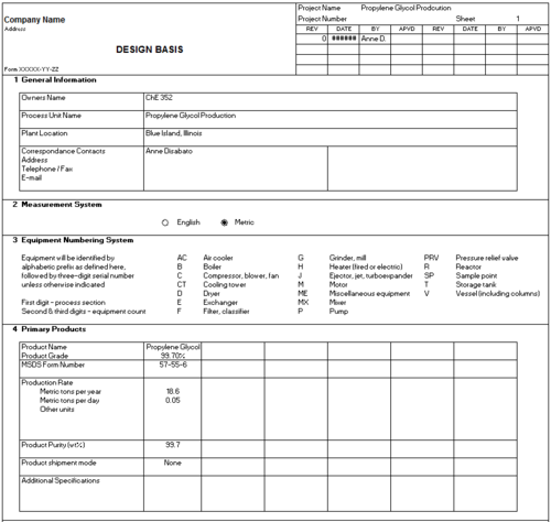
In an effort to build a new bio-product facility for Evanston Chemical, Team BAT is considering producing 99.7% propylene glycol solution. Team BAT designed a small-scale process to use the crude glycerin waste from an up-steam biodiesel facility. It was assumed that capital is available at 12%.
Research on an industrially available propylene glycol manufacturing process, patented by GTC Technology, and a universal process for purifying crude glycerin were used guided the final design (Ding et al., 2013; Xiao et al., 2013). The facility is divided into two sub-processes: pre-treatment of crude glycerin and continuous hydrogenolysis of glycerin to propylene glycol. Microsoft Visio and Aspen HYSYS were used to design the process flow diagram and simulate the production. All other calculations were performed in Microsoft Excel. The plant was designed to operate safely, and have minimal environmental impact.
Team BAT’s plant produces 18.6 tonnes per year of 99.7% propylene glycol. Economic analysis predicts a net present value of - $4.2 million on a twenty-year basis. Based on this analysis, the proposed propylene glycol production facility would be not be economically viable without considerable scale-up and optimization.
Introduction
Propylene glycol, C3H8O2, is a non-corrosive, non-toxic, low volatility liquid, used as chemical feedstock for the production of unsaturated polyester resins, and in the food, beverage, cosmetic, and pharmaceutical industry (Propylene-glycol.com). The freezing point of water is lowered when mixed with propylene glycol, and the latter is therefore used as an anti-freeze and de-icing fluid. Propylene glycol also lowers vapor pressure, making it an ideal burst protection fluid in pipes and vessels. As a cleaning product additive, propylene glycol acts as a stabilizer for the dirt-removing ingredients and helps retain their function at low temperatures.
In food and beverage products, propylene glycol is mainly used as a solvent and carrier of flavor and color, or as a thickener, clarifier, and stabilizer in items such as beer, salad dressing, and baking mixtures. It provides lipstick with its consistent texture, preserves the homogenous consistency of body lotions containing both oil and water, and ensures that shampoos foam nicely. In the pharmaceuticals industry, propylene glycol is used to solubilize and provide equal distribution of the active ingredient in the formulation.
The market for propylene glycol is currently dominated by Dow Chemical and BASF, with 1.8 million tonnes produced globally in 2011 (Dow.com, a). Assuming a price of $1.16 per lb, the current market value is $3.97 billion per year (Propylene-glycol.com). Evanston Chemical Technology Division challenged their employees to design a bioproducts facility in Blue Island, IL capable of taking advantage of a small fraction of this market.
The goal of this report is to evaluate Team BAT’s design of a propylene glycol plant, to determine if Evanston Chemical should invest in independent production. The design of our plant was driven by current manufacturing processes found in literature. The design is split into two sections for simplicity: batch purification of crude glycerin and continuous hydrogenolysis of glycerin to propylene glycol. The facility, project economics, and process flow diagram were modeled on Aspen, Aspen Process Economic Analyzer, and Microsoft Visio, respectively.
Design Basis
As a part of Evanston Chemicals, Team BAT studied an industrial method of producing propylene glycol through continuous hydrogenolysis as described in the GTC Technology 2013 patent (Ding et al., 2013). Evanston Chemicals corresponding biodiesel facility produces 4,700 lbs / week crude glycerin as a byproduct. With crude glycerin being a commodity in excess, the option of selling crude glycerin will be ignored and the available 4,700 lbs / week will be considered free. Our process was designed to increase biodiesel facility profits by taking advantage of the unwanted crude glycerin byproduct.
Team BAT also considered the Davy Process Technology Limited patent, which uses minimal hydrogen and carried out the reaction in multiple stages (Tuck, 2012). After careful process and market considerations, the GTC process was chosen based on low capital-costs, possible reduced operating costs due to multiple energy integration options, high selectivity in a one-step reaction, and relatively low temperatures.
If the GTC style facility produces the maximum possible 18.6 tonnes per year of propylene glycol, Evanston Chemical will account for less than 0.01% of the market. Team BAT decided not to produce and market additional propylene glycol because it is not the primary objective of the larger biodiesel facility.
Project Economics
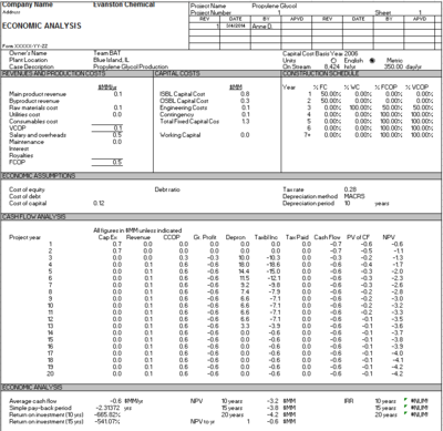
The total fixed capital cost of the current design is $1.3 MM. The ISBL is $800K, and the OSBL is $300K, with an engineering and contingency cost of $200K. This cost, and all other price data, were adjusted for US Midwest and 2014 dollars. The propylene glycol product revenue is a net of $73K. The cost of raw material is $109K, assuming crude glycerol is free, and the annual cost of hydrogen, 37 wt% HCl and NaOH pellets is $60 K, $1K, and $42K, respectively. Other variable capital costs include $5K in continuous process utilities, $500K in salaries and overhead, and $10K in maintenance. The catalyst costs approximately $1,170 per year, and would need to be changed during the annual scheduled downtime.
Using a 10 year MACRS depreciation method, a tax rate of 28% and capital available at 12%, the project is not economically feasible, with the 10 and 20 year NPV coming in at -$3.2 MM and -$4.2 MM, respectively.
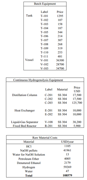
See Appendix I and II for the equipment costs and full economic analysis, respectively. The majority of equipment costing was done on ASPEN Economic Evaluation, with some smaller equipment costs found on Northern Tool & Equipment, Global Industrial, and PKG Equipment (Northerntool.com; Globalindustrial.com; Pkgequipment.com). Utility costs for water and steam were estimated from the City of Chicago website and DailyFinance.com, respectively (Cityofchicago.org; Dailyfinance.com).
Plant Location
The propylene glycol plant will be located at 13636 Western Ave, Blue Island, Illinois 60406. The 10,000 square foot site includes: a truck loading dock, potential rail access, and connections to electric, water, and natural gas. The lease cost is $1,400 per month. Due to other operations at the site, including the biodiesel process, only 2,000 square feet will be allocated to the PG process. The effective lease cost will be spatially prorated for the PG process at $280/month.
Process Overview
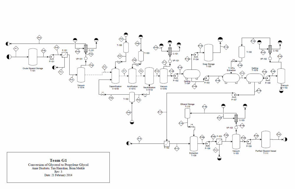
In order to obtain purified glycerin, crude glycerin from the upstream biodiesel is batch purified in a network of vessels. After initial micro-filtration, the glycerin is sent to a vessel that undergoes five stages (A-E) of purification. In Stage A, it is sent to a vacuum evaporation unit, where methanol and water are removed. In Stage B, impurities are converted to more easily separated substances via saponification. After cooling, Stage C consists of acidification to further convert impurities. In stage D, the batch is neutralized. In stage E, the batch undergoes vacuum evaporation for a second time to remove water. Subsequent stages include a settling tank to separate liquid phases and extraction via petroleum ether and denatured ethanol.
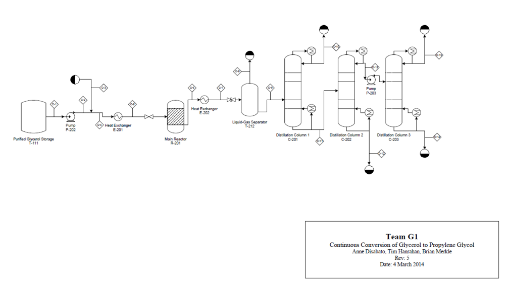
In the GTC Technology process, a feed mixture comprising of purified glycerin, hydrogen, and methanol is preheated in a heat exchanger, and fed to a fixed-bed reactor. The reactor effluent is sent to a heat exchanger, where the stream is cooled. It is then separated into a vapor phase stream and a liquid phase stream. The vapor phase stream is released into the atmosphere. The liquid-phase stream is distilled in three distillation columns to obtain purified propylene glycol.
The following sections explain the above process in detail, outlining the results from HYSYS simulations and the rationale for design choices. See Appendix III for Process Flow Diagram of both the batch purification and continuous process.
Production Schedule
Calculations assume 8,424 hr/yr operation, implying approximately 351 days of continuous operation, leaving adequate time for maintenance. The primary maintenance consideration remains the catalyst regeneration, which must occur every year. This involves emptying the reactor tubes and refilling with new catalyst. A second maintenance consideration is cleaning the batch equipment. This issue is not pressing as the batch sub process is not run at full capacity. The shutdown, cleanup, and refilling should not require more than a week, ensuring compliance with the production schedule.
Design Considerations
Batch Purification
The batch purification of crude glycerin is essential in achieving reactor efficiency and final product purity. In order to accomplish this, ethanol must be added to remove salts. Ethanol has an adverse affect on glycerol solubility; salts have lower solubility in an ethanol-glycerol solution than the corresponding sole-glycerol solution. Ethanol allows a significant amount of salt to precipitate out the solution, which can then be removed by microfiltration. The presence of salts can be detrimental to catalyst activity, making this process important in following the production schedule.
Raw Materials
The raw materials used in the batch purification process include sodium hydroxide pellets (balance water to make 12.5 M basic solution), 37% hydrochloric acid, water, petroleum ether, and denatured ethanol. The sodium hydroxide pellets and hydrochloric acid are laboratory grade. Petroleum ether and denatured ethanol are completely recycled in the batch process. Due to this as an imperfect assumption, the two solvents will need to be replenished twice per year.
Modeling and Sizing the Batch Process
Mass balances on the batch sub process are based a similar analysis by Xiao et al. (2013) published in Industrial & Engineering Chemistry Research. In the paper, the compositions of various samples were analyzed at different stages of the laboratory scale procedure. Those compositions were assumed to be identical our scaled-up batch process, and mass balances were subsequently conducted around each stage. Fatty Acid Methyl Esters (FAME’s) and Glycerides were converted into soap in the saponification stage and Free Fatty Acids (FFA’s) in the acidification stage. The conversion was determined by analyzing the sample compositions before and after the respective stages. The mass and compositions of important streams involved in the batch sub process can be found in Appendix IV.
The amount of sodium hydroxide and hydrochloric acid added in the saponification, acidification, and neutralization stages was calculated from a salt mass balance. The procedures are at pH = 11, pH =1, and pH = 7, respectively. Rather than calculate the amount of acid and base required to reach these conditions, the amount of salt in each sample reported by Xiao et al. was used to back calculate how much acid and base was needed. This methodology makes the mass balance complete and comprehensive, but slightly inaccurate.
The Glycol Package in Aspen HYSYS was used to evaluate various batch process stream densities. Denatured ethanol, along with a mixture of ethanol, methanol, and other additives, were modeled as pure ethanol. Petroleum ether, a solution of hydrocarbons, was modeled as n-decane. FAME’s, FFA’s, and Glycerides were modeled as Methyl Oleate, Oleic Acid, and Triolein, respectively. While these assumptions affect the reported solution density, the results have relatively low dependence on compositional. The batch vessel volumes were found using physical properties from HYSYS and a factor for vapor space of 1.5, or storage capacity of 10 days where applicable, see Appendix V for equipment specification
Batch Process Assumptions and Limitations
Along with the assumptions stated in the previous sections, the following simplifications were made in order to model the batch process. First, a dynamic model was not constructed to simulate the saponification and acidification reactions. Instead, we assumed the laboratory procedure conducted by Xiao et al. (2013) could be scaled up. In addition we assumed a 30 minute cool down time because this information was not reported. Liquid pumps were assumed to transfer liquid from tank to tank in 5 minutes. A Gantt chart for the proposed time schedule of the batch sub process can be seen below, see Appendix VI.
Second, complete recovery of glycerol was assumed throughout the process. The amount of glycerol lost to vacuum evaporation can be considered negligible, but losses associated with liquid-liquid extraction and separation can be significant. This assumption will have the effect of overestimating the amount of glycerol purified, although it should have a negligible effect on the compositions stated in Appendix IV. Third, we assumed perfect removal of water, methanol, ethanol, and petroleum ether. Fourth, the first filter was assumed to have no effect on the overall mass balance. The amount of salts removed in the second filter, in actuality, would be the sum of salt and ash removed by Filters 101 and 102.
Both the mass related assumptions and dynamic assumptions listed above are justifiable when the batch process is treated as a single entity, directly scaled up from the laboratory procedure. It is a substantial limitation, however, when attempting to make beneficial changes necessary to optimize the process. One such example is the extreme conditions associated with the saponification and acidification stages. The conditions are not only dangerous, but produce a difficult and potentially expensive material decision regarding vessel V-101. The short solution was to line a stainless steel vessel with an acidic and basic resistant liner that can withstand elevated temperatures. A quote from the manufacturer PKG Equipment Inc. and can be found in Appendix I. Reducing these extreme conditions could be beneficial to the capital cost, operating cost, and safety conditions.
Batch Optimization
There exist numerous opportunities for optimization in the batch purification process. Over the course of our design, the batch PFD was optimized as follows: the neutralization stage was temporally moved from post-extraction (via petroleum ether) to directly after acidification. This decision is beneficial because it reduces capital costs and improves the safety conditions of the extremely acidic conditions found in the acidification stage to Vessel V-101.
The current batch PFD suggests nine liquid pumps are needed. In actuality, the number of pumps can be consolidated, as they are never running simultaneously. This will reduce the capital cost. Similar rationale can be used to consolidate the number of condensers and vacuum pumps.
As seen in the current Gantt chart, the batch process takes a substantial amount of time to conduct. The first step in scaling up the batch process would be to conduct laboratory experiments to accurately measure the effects of pH on saponification and acidification. Likewise, experiments would be conducted to analyze the necessary time at each stage of the batch process. Consequently, a dynamic, semi-empirical model could be created to analyze and optimize the process.
Other optimization opportunities include: 1. adapting the batch process to accommodate an upstream, unused glycerol stream, 2. analyzing the trade-off between batch vessels being operated under vacuum and heating them to elevated temperatures and 3. using less expensive, industrial grade reagents.
Continuous Conversion to Propylene Glycol
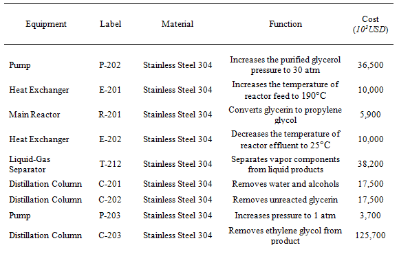
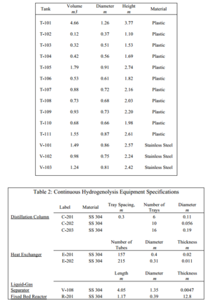
As mentioned in the process overview, the continuous conversion is modeled from the GTC Technology patent. Purified glycerin is heated, sent to a reactor where it is converted to propylene glycol, cooled, and then purified. See Table 1 for a summary of the equipment. In the following sections, the continuous process is explained in detail.
Table 1: Equipment Summary for Continuous Sub-process
Raw Materials
The raw material inputs to the second part of the process, the conversion of purified glycerol to propylene glycol, include purified glycerol and hydrogen gas. The purified glycerol is produced from the batch process described earlier, and is pumped in from a large storage tank. The hydrogen gas, supplied at a pressure of 30 atmospheres, is fed in excess at a rate of 1 kg / hour and is supplied by Praxair at $7 / kg (Dailyfinance.com).
Reactor
Modeling and Sizing
The reactor used to convert glycerol to propylene glycol is modeled from the GTC Technology patent (Ding et al., 2013). The reactor is a fixed-bed reactor packed with catalyst, and operates at 190 °C and 30 atmospheres. The reactor was modeled in HYSYS as a generic conversion reactor using conversion and selectivity data from the article “Kinetics of Hydrogenolysis of Glycerol to Propylene Glycol over Cu-ZnO-Al2O3 Catalysts” by Zhou et al. (2010). The reactor is able to achieve 81.5% conversion of glycerol with selectivity towards propylene glycol of 93%.
Using a LHSV of 4.6 hr-1 and a reactant feed of just under 5 kg / hour, Team BAT determined the size of the reactor to be 0.39 meters in diameter with a tangent length of 1.17 meters, resulting in a total volume of 0.141 cubic meters. The reactor was designed as a stainless steel 304 pressure vessel according to ASME standards, giving a shell thickness of 13 millimeters.
Catalyst
Team BAT decided to use a Cu-ZnO-Al2O3 catalyst with a Cu: ZnO: Al2O3 molar ratio of 1: 1: 0.5. This catalyst was chosen because of its relatively high conversion of glycerol (81.5%) and extremely high selectivity towards propylene glycol (93%) (Zhou et al., 2010). The catalyst was modeled as a collection of spherical particles, each with a diameter of 0.34 millimeters. Using a void fraction in the reactor of 0.5, the total amount of catalyst needed is 467 kg.
Design of Heat Transfer Equipment
There are two main pieces of heat transfer equipment in the continuous part of the process: a heat exchanger to heat the reactor feed to the desired operating conditions as well as a heat exchanger to cool the reactor effluent before the separation equipment.
E-201: Heating Reactor Feed
The first heat exchanger in the continuous reaction process using superheated steam at 600 psi and 300 °C to heat the mixture of glycerol and hydrogen to the desired reactor operating temperature of 190 °C. The heat exchanger was designed following TEMA recommendations as an AEL-type exchanger with the reactant feed being heated on the tube side by the high-pressure steam on the shell side.
This unit requires a heat transfer area of 0.018 square meters and consists of 157 tubes (stainless steel 304) with a 12 mm inner diameter, 17 mm outer diameter and a length of 0.5 meters. These tubes are arranged in a square pitch resulting in a shell diameter of 0.4 meters. The shell is also constructed from stainless steel 304 and has a wall thickness of 20 mm.
E-202: Cooling Reactor Effluent
The second heat exchanger in the continuous process uses cooling water at 10 °C to cool the reactor effluent from 222 °C to room temperature. A reduce in temperature increases separation efficiency. This heat exchanger is also an AEL-type exchanger with the cooling water on the tube side and reactor effluent on the shell side.
This unit requires a heat transfer area of 0.043 square meters and consists of 215 stainless steel 304 tubes with an 8 mm inner diameter, 13 mm outer diameter and a length of 1.5 meters. The shell, also constructed from stainless steel 304, has a diameter of 0.31 meters and has a wall thickness of 11 mm.
Product Purification
After the glycerol is converted to propylene glycol in the fixed-bed reactor, the desired product must be separated from the other components, including water, unreacted hydrogen and glycerol, as well as unwanted side products, such as methanol, acetol and ethylene glycol. This is achieved using four different pieces of equipment: a liquid-gas separator and three distillation columns in series.
Liquid-Gas Separator
After the reactor effluent is cooled, it is sent to the first of four separation units. The first unit takes the multiphase stream and separates the vapor components (unreacted hydrogen and other trace components) from the liquid products. The liquid-gas separator was designed as a pressure vessel that can hold 30 minutes worth of product. The unit has a diameter of 1.35 meters and a height of 4.05 meters, giving the vessel a total volume of just over 5.8 cubic meters. The vessel is constructed from stainless steel 304 and has a wall thickness of 4.7 mm. The vapor stream is vented to the atmosphere and the liquid products are sent to a series of three distillation columns.
C-201 Distillation Column
The first of three distillation columns separates water and alcohols (methanol and acetol) from the unreacted glycerol, ethylene glycol, and the propylene glycol product. The column operates at atmospheric pressure and has 6 sieve trays, with the feed entering on the second tray from the top. The column has a height of 1.8 meters and a diameter of 0.11 meters, and the energy consumed and generated from the reboiler and condenser are 1.63 kW and 1.14 kW respectively.
C-202 Distillation Column
The second distillation column separates the unreacted glycerol, which can be sent back to the batch process to be purified, from the unreacted ethylene glycol and propylene glycol products, which come off the top of the column and are condensed and pumped to the last column. The column operates at atmospheric pressure and has 10 sieve trays, with the feed entering on the fifth tray from the top. The column has a height of 3 meters and a diameter of 5.6 centimeters, and the energy consumed and generated from the reboiler and condenser are 1.29 kW and 1.25 kW, respectively.
C-203 Distillation Column
The last distillation column separates the propylene glycol product from the ethylene glycol. The column operates at atmospheric pressure and has 16 sieve trays. The feed to the third column comes from the overhead of the second column, and enters on the sixth tray from the top. The column has a height of 4.8 meters and a diameter of 0.19 meters, and the energy consumed and generated from the reboiler and condenser are each 3.73 kW. The propylene glycol is taken off the top of the tower and has a purity of 99.7 wt%.
Assumptions and Limitations
A number of assumptions were made in designing the continuous part of the process. In the reactor, it was assumed that the conversion and selectivity presented by Zhou et al are applicable for the slightly scaled-up process discussed above. It was also assumed that the production of side products other than acetol and ethylene glycol is negligible, though in reality that may not be true. It was also assumed that the design of each piece of equipment is applicable despite the extremely small scale of the proposed process.
Sensitivity Analysis
A sensitivity analysis is necessary to analyze the viability of any process. While our process is not economically feasible, a sensitivity analysis was conducted to examine the effects of uncertain parameters. If the sale price of propylene glycol increases by 20%, the change to our NPV is negligible; the process is still unfeasible. Similarly, if the ISBL capital costs or OSBL capital cost are decreased by 20%, the process is still unable to make a profit in the first 20 years. If the main product revenue increases to $900K, the NPV will be positive after 7 years.
Safety and Environment
Chemical plant safety is one of the primary requirements in process design at Evanston Chemical. From the delivery of raw materials to final product transport, the employees of Evanston Chemical have the right to a safe workplace. All OSHA standards for exposure, personal protective equipment, and operation control will be strictly followed. Pressures are kept low and should not constitute a major hazard; moreover, vessel wall thickness exceeds ASME BPV code requirements for maximum safety. All process equipment will be fitted with pressure relief valves for safety. The highest temperature is 275 °C, found in the second distillation column bottoms. In the event of a sudden temperature increase, the valves can be shut off.
Neither glycerin nor propylene glycol constitutes a major threat to safety. As additives to consumer products, the chemicals are only slightly dangerous in large quantities (Dow.com, b). Eye contact may result in temporary irritation; corneal injury is unlikely. Prolonged skin contact is unlikely to cause irritation. Inhalation of vapors appears to present no significant hazard in ordinary applications, and this is reflected in the fact that OSHA has not found it necessary to establish a permissible exposure level in the workplace.
The lifecycle of propylene glycol production is relatively environmentally friendly. The fundamental raw material, glycerin, is obtained from a up-stream facility which converts local restaurant vegetable oil into biodiesel. The environmental cost of transportation is minimized.
The product, propylene glycol, is considered to be practically nontoxic to fish on an acute basis (LC50 > 100 mg/L) and practically nontoxic to aquatic invertebrates (Dow.com, b). Additionally, the products of PG degradation are less toxic than the product itself.
Conclusion
Team BAT’s proposed plant will produce 18.6 tonnes/yr of 99.7 wt% propylene glycol. Economic analysis of the proposed plant, on a twenty year basis, yields a net present value (NPV) of -$4.2 MM. Hence, the current project is not economically feasible. Please see above Design Consideration sections on optimization for possible ways to improve profitability. While optimization can improve efficiency and reduce costs, scaling-up the process is recommended.
References
Cityofchicago.org. Water Sewer Rates [Internet]. Chicago: City of Chicago; c2010-15 [cited 2015 Feb 26]. Available from: http://www.cityofchicago.org/city/en/depts/water/provdrs/cust_serv/svcs/know_my_water_sewerrates.html.
Dailyfinance.com [Internet]. New York: AOL Inc.; c2015 [cited 2015 Feb 26]. Available from: http://www.dailyfinance.com/.
Ding Z, Chiu J, Jin W, inventor; GTC Technology US LLC, assignee. Process for converting glycerin into propylene glycol. US Patent 08394999 B2. 2013 Mar 12.
Dow.com. About propylene glycols [Internet]. Midland: The Dow Chemical Company; c1995-2015a [cited 2015 Feb 26]. Available from: http://www.dow.com/propyleneglycol/about/.
Dow.com. Product Safety Assessment [Internet]. Midland: The Dow Chemical Company; c1995-2015b [cited 2015 Feb 26]. Available from: http://msdssearch.dow.com/PublishedLiteratureDOWCOM/dh_091a/0901b8038091a41a.pdf?filepath=productsafety/pdfs/noreg/233-00490.pdf&fromPage=GetDoc.
Globalindustrial.com [Internet]. Global Equipment Company Inc.; c2015 [cited 2015 Feb 26]. Available from: http://www.globalindustrial.com/.
Northerntool.com [Internet]. Burnsville: Northern Tool + Equipment [cited 2015 Feb 26]. Available from: http://www.northerntool.com/.
Pkgequipment.com [Internet]. Rochester: PKG Equipment Inc.; c2013 - [cited 2015 Feb 26]. Available from: http://www.pkgequipment.com/index.html.
Praxair.com [Internet]. Danbury: Praxair Technology, Inc.; c2013-15 [cited 2015 Feb 26]. Available from: http://www.praxair.com/.
Propylene-glycol.com [Internet]. Brussels: PO/PG Sector group of Cefic [cited 2015 Feb 26]. Available from: http://www.propylene-glycol.com/.
Sciencelab.com. Material Safety Data Sheet Propylene glycol MSDS [Internet]. Houston: ScienceLab.com, Inc.; c1997-2005 [cited 2015 Feb 26]. Available from: https://www.sciencelab.com/msds.php?msdsId=9927239.
Tuck MWM, inventor; Davy Process Technology Limited, assignee. Process for the hydrogenation of glycerol to propylene glycol. US patent 08227646 B2. 2012 Jul 24.
Xiao Y, Xiao G, Varma A. A universal procedure for crude glycerol purification from different feedstocks in biodiesel production: experimental and simulation study. Ind Eng Chem Res. 2013;52(39):14291-6.
Zhou Z, Li X, Zeng T, Hong W, Cheng Z, Yuan W. Kinetics of hydrogenolysis of glycerol to propylene glycol over Cu-ZnO-Al2O3 catalysts. Chin J Chem Eng. 2010;18(3);384-90.
Appendix I: Equipment Costs
Appendix II: Economic Analysis
Appendix III: Process Flow Diagrams
Batch Sub-process PFD:
Continuous Sub-process PFD:
Appendix IV: Mass and Energy Balances
For Mass and Energy Balances for both the batch and continuous sub-processes, please refer to the hard copy of the final report.
